- FirstAp
- RegAddr
- Status
- Arith
- MidGoto
- LowGoto
- CondJump
- VarMani
- VarArray
- StackOps
- FirstCal
- StakCall
- CallBUp
- Table0
- ArbTable
- SmallTbl
- StateMC
- LEDOn
- Current Consumption Check
- Debounce
- PinChg
- TimeEnd
- Decouple
- WDT
- PowerUp
- Reset
- TMR0
- Random
- Sleep
- DiffOsc
- EEPROM
- SHORT
- ADCLess
- ADC
- VLadder
- PWMOut
- Cylon
- TMR0Int
- LEDPWM
- IntDeb
- TrueRS
- BasicRS
- SimpRS
- 3RS
- Debug
Useful Code Snippets and Macros

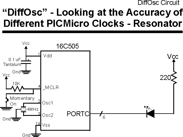
"DiffOsc" Experiment
Most PICmicro® MCU part numbers can take advantage of several different types of oscillators. In this experiment, the PIC16C505 is used to demonstrate the built in, external crystal and external ceramic resonator 4 MHz oscillators. The experiment is designed to run for sixteen minutes (960 or B'001111000000' Seconds), at which time, the difference between it and a calibrated clock is checked.
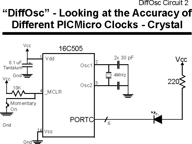
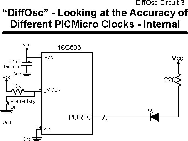
The experiment is run three times, with each of the three different
circuits shown below:
The parts needed for this experiment are listed in the table:
| Part | Description |
|---|---|
| PICmicro® MCU | PIC16C505-JW |
| Vdd/Vss Decoupling Capacitor | 0.1 uF (Any Type) |
| _MCLR Pull Up Resistor | 10K, 1/4 Watt |
| 4 MHz Crystal | "Parallel Cut" |
| 27-33 pF Capacitorys | 2x Any Type |
| 4 MHz Ceramic Resonator | Three Leaded Ceramic Resonator with Built in 27-33pF Capacitors |
| LED Current Limiting Resistors | 6x 220W, 1/4 Watt |
| LED Display | 10 LED "Bargraph" Recommended |
| Breadboard | Any Type |
| +5 Volt "Vcc" Power Supply | Any Type |
Using a breadboard, the experiment is wired using the guide:
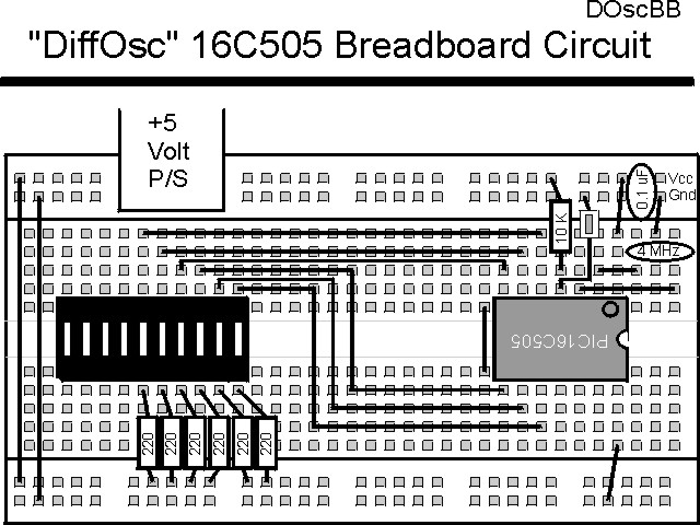
This circuit can be built on a EMU-II or YAP-II, but note that the oscillator will have to be connected as shown in the breadboard diagram.
The source code listed below can be accessed from the CD-ROM by clicking Here. Note that the first instruction (movwf OSCCAL) is always present; even when the external crystal or external ceramic resonator is being used for the experiment.
 title  "DiffOsc - Increment PORTC Once a Minute"
;
;  This Application Tests the time keeping Ability of the 16C505
;   With Different Clocks by updating the PORTC Value once every
;   1,000,000 Cycles (or One Second).
;
;
;  Hardware Notes:
;   PIC16C505 Running at 4 MHz with Different Clocks
;   _MCLR is Pulled Up
;   All 6 bits of PORTC are Pulled up and Connected to LEDs
;   PORTC.5 ("TOCK1") I/O set to I/O
;
;  Myke Predko
;  99.12.29
;
  LIST P=16C505, R=DEC
  INCLUDE "p16c505.inc"

;  Register Usage
 CBLOCK 0x010                 ;  Start Registers at End of the Values
Dlay:3				;  Counter for 1,000,000 Cycles
 ENDC


 PAGE
; __CONFIG _MCLRE_ON & _CP_OFF & _WDT_OFF & _XT_OSC
 __CONFIG _MCLRE_ON & _CP_OFF & _WDT_OFF & _IntRC_OSC_RB4EN

;  Mainline of DiffOsc
  org    0

  movwf   OSCCAL			;  Save the Oscillator Calibration Value

  movlw   0x0FF ^ (1 << T0CS)	;  Turn Off TOCK1 (RC5) Pin Input
  option

  movlw   0x0FF			;  Turn Off the LEDs on PORTC
  movwf   PORTC

  movlw   0x0C0			;  Turn on the PORTC Pins
  tris    PORTC

Loop					;  Loop Here Every 60,000,000 Cycles

  call    Delay

  decf    PORTC, f		;  "Increment" the LED output

  goto    Loop

Delay					;  Delay 1,000,000 - 5 Cycles

  movlw   4				;  Loop 4x
  movwf   Dlay + 2

DelayLoop
  movlw   0x0C4			;  249,993 Cycles Delay
  movwf   Dlay + 1
  movlw   0x04E
  movwf   Dlay
  decf    Dlay, f			;  Delay 5 Cycles for Each Loop
  btfsc   STATUS, Z
   decfsz Dlay + 1, f
    goto  $ - 3

  decfsz  Dlay + 2, f		;  Loop 4x
   goto   DelayLoop

  goto    $ + 1			;  Have to Remove 8 Cycles
  goto    $ + 1
  goto    $ + 1
  goto    $ + 1

  return


 end