- FirstAp
- RegAddr
- Status
- Arith
- MidGoto
- LowGoto
- CondJump
- VarMani
- VarArray
- StackOps
- FirstCal
- StakCall
- CallBUp
- Table0
- ArbTable
- SmallTbl
- StateMC
- LEDOn
- Current Consumption Check
- Debounce
- PinChg
- TimeEnd
- Decouple
- WDT
- PowerUp
- Reset
- TMR0
- Random
- Sleep
- DiffOsc
- EEPROM
- SHORT
- ADCLess
- ADC
- VLadder
- PWMOut
- Cylon
- TMR0Int
- LEDPWM
- IntDeb
- TrueRS
- BasicRS
- SimpRS
- 3RS
- Debug
Useful Code Snippets and Macros

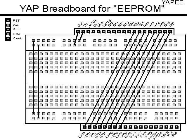
"EEPROM" Experiment
In some applications, you will want to use the PICmicro® MCU's built in data EEPROM for storing calibration values. In order to do this, the EEPROM should be loaded with a predetermined value. In this experiment, I create an data EEPROM four byte "Check Area" along with a counter that increments each time the application resets.
The experiment uses the circuit shown below. Note that you may want to put
a 0.1 uF capacitor across the switch leads to minimize switch bouncing which can cause
problems if the application is reset during the EEPROM reads.

The parts needed for this experiment are the same as (PowerUp's) and listed in the table:
| Part | Description | Required for the YAP-II |
|---|---|---|
| PICmicro® MCU | PIC16F84-04/P PIC16F877-04/P |
In Socket |
| Vdd/Vss Decoupling Capacitor | 0.1 uF (Any Type) | No |
| _MCLR Pull Up Resistor | 10K, 1/4 Watt | No |
| 4 MHz Ceramic Resonator | Three Leaded Ceramic Resonator with Built in 27-33pF Capacitors | No |
| _MCLR Push Button | Momentary On/Modified for Breadboard | No - Internal Reset Used |
| (Optional) _MCLR Filter Capacitor | 0.1 uF (Any Type) | No - Internal Reset Used |
| PORTB LED Current Limiting Resistors | 8x 220W, 1/4 Watt | No - "LED1" Used |
| PORTB LED | 10 LED "Bargraph" Recommended | No - "LED1" through "LED9" Used |
| Breadboard | Any Type | No |
| +5 Volt "Vcc" Power Supply | Any Type | No |
Using a breadboard, the experiment is wired using the guide:

If the EMU-II or YAP-II is used, the experiment is wired as:
The EEPROM Read code could be changed into the Macro:
EERead Macro Address          ;  PIC16F84 EEPROM Data "Read" Macro
  movlw  Address              ;  Look for "Check" Bytes in Data EEPROM
  movwf  EEADR
  bsf    STATUS, RP0
  bsf    EECON1, RD           ;  Read and Compare the First Byte
  bcf    STATUS, RP0
  movf   EEDATA, w
 endm                         ;  "w" contains EEPROM Contents at "Address"
The EEPROM Write code could be changed into the Macro:
EEWrite Macro Address, Data   ;  PIC16F84 EEPROM Data "Write" Macro
  movlw  Address
  movwf  EEADR
  movlw  Data
  movwf  EEDATA
  bsf    STATUS, RP0
  bcf    STATUS, C            ;  Use Carry to save "GIE"
  btfsc  INTCON, GIE
   bsf   STATUS, C
  bcf    INTCON, GIE          ;  No Interrupts during the sequence below
  bcf    INDF, WRERR          ;  Make Sure Write Error Bit is Reset
  bsf    INDF, WREN           ;  Enable the Write
  movlw  0x055                ;  #### - Required Write Sequence
  movwf  EECON2 ^ 0x080       ;  ####
  movlw  0x0AA                ;  ####
  movwf  EECON2 ^ 0x080       ;  ####
  bsf    EECON1 ^ 0x080, WR   ;  #### - End of Required Write Sequence
  btfsc  STATUS, C            ;  Can Enable Interrupts
   bsf   INTCON, GIE
  btfss  INDF, EEIF           ;  Wait for Finished Interrupt Request
   goto  $ - 1
  bcf    STATUS, RP0          ;  Return to Bank 0
  bcf    INDF, WREN
  bcf    INDF, EEIF
 endm
The "EEWrite" macro uses the Carry flag to save the state of the Interrupt Enable
bit (GIE). This is not a problem in this macro because there are no
instructions executed in the critically timed "Required Write Sequence" that change
any of the status register.
The source code listed below can be accessed from the CD-ROM by clicking Here. Note the use of the "de" statement which will not be allowed by the El Cheapo, YAP-II or EMU-II - if these programmers are used, then this line should be deleted.
 title  "EEPROM - Show Contents of an EEPROM Counter on Reset"
;
;  This Application checks four bytes in the Data EEPROM to see
;   if they are at an expected value and then increments an
;   EEPROM counter and displays it.  If the Data EEPROM Check
;   bytes are not true, then they are set and the LEDs on PORTB
;   are flashed.
;
;  Flash Memory is Organized as:
;  Byte 0 - 0x0FF
;  Byte 1 - 0x000
;  Byte 2 - 0x0AA
;  Byte 3 - 0x055
;  Byte 4 - EEPROM Counter
;
;  Hardware Notes:
;   PIC16F84 Running at 4 MHz
;   _MCLR is Pulled Up with a Momentary On Pull Down Switch
;   All 8 bits of PortB are Pulled up and Connected to LEDs
;
;  Myke Predko
;  99.12.28
;
  LIST R=DEC
  INCLUDE "p16f84.inc"

;  Register Usage
 CBLOCK 0x020                 ;  Start Registers at End of the Values
Dlay:2				;  Two Bytes for Flashing Delay
 ENDC


 PAGE
 __CONFIG _CP_OFF & _XT_OSC & _PWRTE_ON  & _WDT_OFF

;  Mainline of EEPROM
  org    0

  bsf    STATUS, RP0
  clrf   TRISB ^ 0x080		;  Make All 8 PortB Bits Output
  bcf    STATUS, RP0

  movlw  EECON1			;  Use FSR To point to EECON1
  movwf  FSR			;  To Avoid Going Back and Forth

  movlw  0				;  Look for "Check" Bytes in Data EEPROM
  movwf  EEADR
  bsf    INDF, RD			;  Read and Compare the First Byte
  movf   EEDATA, w
  xorlw  0x0FF
  btfss  STATUS, Z
   goto  WrongEEPROM		;  Not 0x0FF - Reset the EEPROM and Continue
  movlw  1
  movwf  EEADR
  bsf    INDF, RD			;  Read and Compare the Second Byte
  movf   EEDATA, w
  xorlw  0x000
  btfss  STATUS, Z
   goto  WrongEEPROM
  movlw  2
  movwf  EEADR
  bsf    INDF, RD			;  Read and Compare the Third Byte
  movf   EEDATA, w
  xorlw  0x0AA
  btfss  STATUS, Z
   goto  WrongEEPROM
  movlw  3
  movwf  EEADR
  bsf    INDF, RD			;  Read and Compare the Fourth Byte
  movf   EEDATA, w
  xorlw  0x055
  btfss  STATUS, Z
   goto  WrongEEPROM

;  Check Data is Correct - Display Current Contents and Increment Them

  movlw  4
  movwf  EEADR
  bsf    INDF, RD
  comf   EEDATA, w		;  Get the Complemented Data for LEDs
  movwf  PORTB

  xorlw  0x0FF			;  Increment and Store the Byte Back
  addlw  1
  movwf  EEDATA
  call   EEWrite			;  Write to the EEPROM Data

  goto   $				;  Finished, Endless Loop

WrongEEPROM				;  Rewrite the Contents of Data EEPROM
  movlw  0				;  Write the First Byte
  movwf  EEADR
  movlw  0x0FF
  movwf  EEDATA
  call   EEWrite

  movlw  1				;  Write the Second Byte
  movwf  EEADR
  movlw  0x000
  movwf  EEDATA
  call   EEWrite

  movlw  2				;  Write the Third Byte
  movwf  EEADR
  movlw  0x0AA
  movwf  EEDATA
  call   EEWrite

  movlw  3				;  Write the Fourth Byte
  movwf  EEADR
  movlw  0x055
  movwf  EEDATA
  call   EEWrite

  movlw  4				;  Reset the Counter
  movwf  EEADR
  movlw  0x000
  movwf  EEDATA
  call   EEWrite

Loop					;  Flash the LEDs in this Case

  call   Delay			;  Delay 200 msecs

  comf   PORTB, f			;  Complement the Contents of PORTB

  goto   Loop

;  Subroutines

Delay					;  Delay 200 msecs

  clrf   Dlay
  clrf   Dlay + 1
  decfsz Dlay, f
   goto  $ - 1
  decfsz Dlay + 1, f
   goto  $ - 3

  return

EEWrite				;  Write EEData into EEPROM at Address EEADR

  bsf    STATUS, RP0
  bcf    INDF, WRERR		;  Make Sure Write Error Bit is Reset
  bsf    INDF, WREN		;  Enable the Write
  movlw  0x055			;  #### - Required Write Sequence
  movwf  EECON2 ^ 0x080		;  ####
  movlw  0x0AA			;  ####
  movwf  EECON2 ^ 0x080		;  ####
  bsf    EECON1 ^ 0x080, WR	;  #### - End of Required Write Sequence

  btfss  INDF, EEIF		;  Wait for Finished Interrupt Request
   goto  $ - 1

  bcf    STATUS, RP0		;  Return to Bank 0
  bcf    INDF, WREN
  bcf    INDF, EEIF

  return

 org     0x02100			;  #### - EEPROM Set Here
  de	 0x0FF, 0x0FF, 0x0FF, 0x0FF, 0x0FF  ;  NOTE Note Accessible by all Programmers


 end