- FirstAp
- RegAddr
- Status
- Arith
- MidGoto
- LowGoto
- CondJump
- VarMani
- VarArray
- StackOps
- FirstCal
- StakCall
- CallBUp
- Table0
- ArbTable
- SmallTbl
- StateMC
- LEDOn
- Current Consumption Check
- Debounce
- PinChg
- TimeEnd
- Decouple
- WDT
- PowerUp
- Reset
- TMR0
- Random
- Sleep
- DiffOsc
- EEPROM
- SHORT
- ADCLess
- ADC
- VLadder
- PWMOut
- Cylon
- TMR0Int
- LEDPWM
- IntDeb
- TrueRS
- BasicRS
- SimpRS
- 3RS
- Debug
Useful Code Snippets and Macros

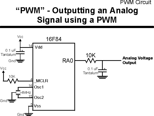
"PWMOut" Experiment
The second method of outputting an analog voltage is to send a PWM signal into a low-pass filter. The advantages of this method over the voltage ladder is the ability to have much better granularity on the output and the circuit is much simpler. The downside is the extra cycles required by the PICmicro® MCU to control the PWM output (although this could be reduced by using the CCP hardware available in some PICmicro MCU part numbers).
In this experiment, I dedicate the PICmicro MCU to driving out the PWM signal
using the circuit shown below:
The parts needed for this experiment are listed in the table:
| Part | Description | Required for the YAP-II/EMU-II? |
|---|---|---|
| PICmicro® MCU | PIC16F84-04/P PIC16F877-04/P |
In Socket |
| Vdd/Vss Decoupling Capacitor | 0.1 uF (Any Type) | No |
| _MCLR Pull Up Resistor | 10K, 1/4 Watt | No |
| 4 MHz Ceramic Resonator | Three Leaded Ceramic Resonator with Built in 27-33pF Capacitors | No |
| 10K 1/4 Watt resistor | Any Type | Yes |
| 0.1 uF Capacitor | Any Type | Yes |
| Breadboard | Any Type | No |
| +5 Volt "Vcc" Power Supply | Any Type | No |
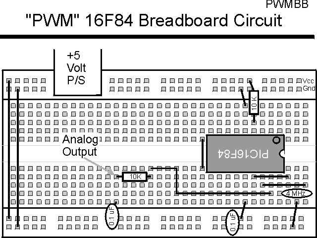
Using a breadboard, the experiment is wired using the guide:
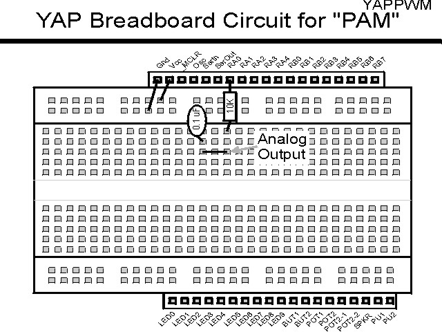
If the EMU-II or YAP-II is used, the experiment is wired as:
The source code listed below can be accessed from the CD-ROM by clicking Here.
 title  "PWMOut - Output a PWM Analog Voltage"
;
;  This Application simply Outputs an Analog Voltage by Driving a
;   Resistor/Capacitor ("RC") Network with a PWM signal.
;
;  The PWM runs at 20 kHz, with a Duty Cycle range from 0 to 100%
;   Demonstrated.
;  This is an Actual PWM Duty Cycle Range of 0 to 50 Instructions/usecs
;
;  Hardware Notes:
;   This application runs on a 16F84 executing at 4 MHz
;   _MCLR is tied through a 4.7K Resistor to Vcc and PWRT is Enabled
;   A 10K Resistor/0.1 uF Capacitor Network is connected to RA0 to Show
;    the PWM in Operation
;
;  Myke Predko
;  99.12.27
;
  LIST R=DEC
 ifdef __16F84
  INCLUDE "p16f84.inc"
 else
 ifdef __16F877
  INCLUDE “p16f877.inc”
 endif

;  Registers
 CBLOCK 0x020
LoopNumber
PWMOn					;  PWM "On Value"
PWMOff
 ENDC

#define PWM PORTA, 0		;  LED on PORTB.0


 ifdef __16F84
 __CONFIG _CP_OFF & _WDT_OFF & _XT_OSC & _PWRTE_ON
 else
 __CONFIG _CP_OFF & _WDT_OFF & _XT_OSC & _PWRTE_ON & _DEBUG_OFF & _LVP_OFF & _BODEN_OFF
 endif

  PAGE
;  Mainline of pwmout

 org     0

  nop

  movlw  2				;  Start the PWM with Nothing
  movwf  PWMOn

  clrf   LoopNumber		;  Output Each Voltage Level for 10
;   Iterations
  bcf    PWM                  ;  Make the PWM "off" Initially
  bsf    STATUS, RP0          ;  Goto Bank 1 to set Port Direction
  bcf    PWM                  ;  Set PWM Pin to Output
  bcf    STATUS, RP0          ;  Go back to Bank 0

Loop					;  Loop Here and Output the PWM

  bsf    PWM			;  Turn on the PWM

  movf   PWMOn, w			;  Calculate Delay Time
  sublw  12
  movwf  PWMOff

  decf   PWMOn, w			;  Display the Data Here
  addlw  0x0FF			;  Take One Away
  btfss  STATUS, Z
   goto  $ - 2

  bcf    PWM			;  Turn OFF PWM

  incf   LoopNumber, f

  btfsc  STATUS, Z		;  Looped 256x?
;  btfsc  LoopNumber, 0		;  Looped 1x?
   goto  NewLoop

OffLoop

  decf   PWMOff, w		;  No, Just Output It
  addlw  0x0FF
  btfss  STATUS, Z
   goto  $ - 2

  goto   Loop

NewLoop				;  Increment the Output Value

  clrf   LoopNumber

  incf   PWMOn, w			;  Increment the Value
  xorlw  8
  btfsc  STATUS, Z		;  At 8?
   movlw 2 ^ 8			;   Yes - Reset
  xorlw  8
  movwf  PWMOn

  movlw  3				;  "NewLoop" takes 3 Cycles of Time
  subwf  PWMOff, f

  goto   OffLoop


 end