- FirstAp
- RegAddr
- Status
- Arith
- MidGoto
- LowGoto
- CondJump
- VarMani
- VarArray
- StackOps
- FirstCal
- StakCall
- CallBUp
- Table0
- ArbTable
- SmallTbl
- StateMC
- LEDOn
- Current Consumption Check
- Debounce
- PinChg
- TimeEnd
- Decouple
- WDT
- PowerUp
- Reset
- TMR0
- Random
- Sleep
- DiffOsc
- EEPROM
- SHORT
- ADCLess
- ADC
- VLadder
- PWMOut
- Cylon
- TMR0Int
- LEDPWM
- IntDeb
- TrueRS
- BasicRS
- SimpRS
- 3RS
- Debug
Useful Code Snippets and Macros

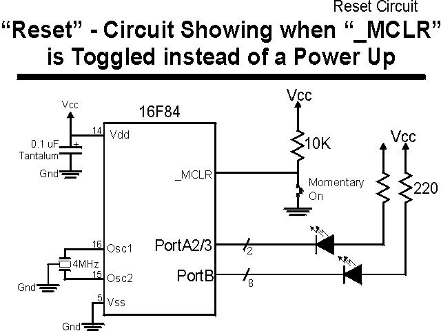
"Reset" Experiment
This experiment shows the value of _TO and _PD in the PICmicro® MCU's STATUS register. These bits are used to indicate the reason for a device reset for all cases except when the _MCLR is cycled. This experiment shows the value of the two bits before and after a _MCLR reset as well as present how file register contents can be used to check whether or not the reset was caused by a Power Up (or other reset) or _MCLR.
The experiment uses the circuit shown below:
The parts needed for this experiment are the same as (PowerUp's) and listed in the table:
| Part | Description | Required for the YAP-II/EMU-II? |
|---|---|---|
| PICmicro® MCU | PIC16F84-04/P PIC16F877-04/P |
In Socket |
| Vdd/Vss Decoupling Capacitor | 0.1 uF (Any Type) | No |
| _MCLR Pull Up Resistor | 10K, 1/4 Watt | No |
| 4 MHz Ceramic Resonator | Three Leaded Ceramic Resonator with Built in 27-33pF Capacitors | No |
| RA0 Push Button | Momentary On/Modified for Breadboard | No - "BUT1" Used |
| PORTB LED Current Limiting Resistors | 10x 220W, 1/4 Watt | No - "LED1" Used |
| PORTA/PORTB LED | 10 LED "Bargraph" Recommended | No - "LED1" through "LED9" Used |
| Breadboard | Any Type | No |
| +5 Volt "Vcc" Power Supply | Any Type | No |
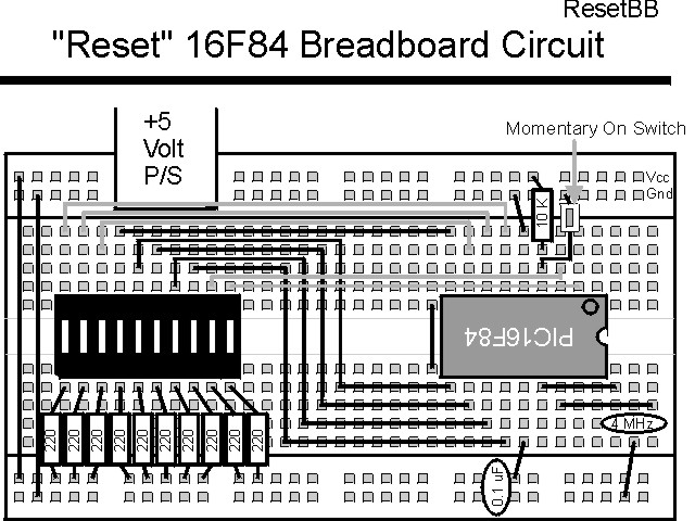
Using a breadboard, the experiment is wired using the guide:
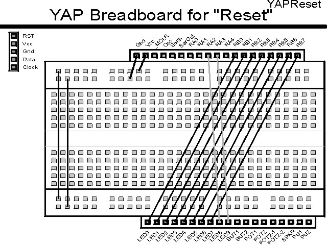
If the EMU-II or YAP-II is used, the experiment is wired as:
The source code listed below can be accessed from the CD-ROM by clicking Here.
 title  "Reset - Turn on PORTB LEDs if _MCLR Reset"
;
;  This Application checks four bytes to see if they are at an
;   expected value and turns on all the LEDs on PORTB if this is
;   true, else the LEDs are turned off.
;
;
;  Hardware Notes:
;   PIC16F84 Running at 4 MHz
;   _MCLR is Pulled Up
;   All 8 bits of PortB are Pulled up and Connected to LEDs
;   PORTA.2 is Pulled up and Connected to a LED for _PD
;   PORTA.3 is Pulled up and Connected to a LED for _TO
;
;  Myke Predko
;  99.12.26
;
  LIST R=DEC
 ifdef __16F84
  INCLUDE "p16f84.inc"
 else
 ifdef __16F877
  INCLUDE "p16f877.inc"
 endif

;  Register Usage
 CBLOCK 0x020                 ;  Start Registers at End of the Values
Check:4				;  Four Byte Check Value
 ENDC


 PAGE
 ifdef __16F84
 __CONFIG _CP_OFF & _WDT_OFF & _XT_OSC & _PWRTE_ON
 else
 __CONFIG _CP_OFF & _WDT_OFF & _XT_OSC & _PWRTE_ON & _DEBUG_OFF & _LVP_OFF & _BODEN_OFF
 endif

;  Mainline of Reset
  org    0

  nop

  rrf    STATUS, w		;  Save the Current STATUS Value
  xorlw  0x0FF			;  Invert to Show Value
  movwf  PORTA

  bsf    STATUS, RP0
  clrf   TRISB ^ 0x080		;  Make All 8 PortB Bits Output
  movlw  0x013			;  Make RA2 and RA3 Outputs/RA0 Input
  movwf  TRISA ^ 0x080
  bcf    STATUS, RP0

  movf   Check, w			;  Check for First/Subsequent PICmicro
  xorlw  0x0FF			;   Reset
  btfss  STATUS, Z
   goto  FirstTime		;  No Match - Subsequent Reset
  movf   Check + 1, w		;  Check Second Byte
  xorlw  0x000
  btfss  STATUS, Z
   goto  FirstTime
  movf   Check + 2, w
  xorlw  0x0AA
  btfss  STATUS, Z
   goto  FirstTime
  movf   Check + 3, w
  xorlw  0x055
  btfss  STATUS, Z
   goto  FirstTime

  clrf   PORTB			;  Match - Turn on LEDs

  goto   $ 				;  Finished – Infinite Loop

FirstTime				;  No Match, Set up Values/Turn off LEDs

  movlw  0x0FF
  movwf  PORTB			;  Turn Off LEDs

  movwf  Check			;  Save the Check Values
  clrf   Check + 1
  movlw  0x0AA
  movwf  Check + 2
  movlw  0x055
  movwf  Check + 3

  goto   $				;  When Finished, Infinite Loop


 end