- FirstAp
- RegAddr
- Status
- Arith
- MidGoto
- LowGoto
- CondJump
- VarMani
- VarArray
- StackOps
- FirstCal
- StakCall
- CallBUp
- Table0
- ArbTable
- SmallTbl
- StateMC
- LEDOn
- Current Consumption Check
- Debounce
- PinChg
- TimeEnd
- Decouple
- WDT
- PowerUp
- Reset
- TMR0
- Random
- Sleep
- DiffOsc
- EEPROM
- SHORT
- ADCLess
- ADC
- VLadder
- PWMOut
- Cylon
- TMR0Int
- LEDPWM
- IntDeb
- TrueRS
- BasicRS
- SimpRS
- 3RS
- Debug
Useful Code Snippets and Macros

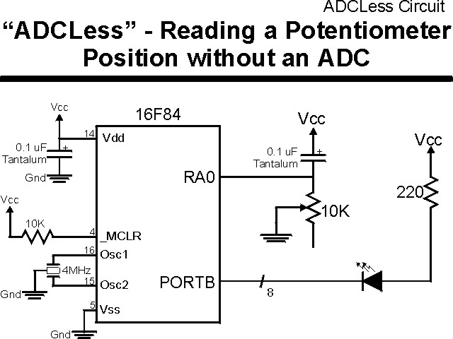
"ADCLess" Experiment
This experiment demonstrates how the digital I/O pins of the PICmicro can be used to "read" the position of a potentiometer. The original design for this application comes from the Parallax Basic Stamp 2.
The potentiometer read code could be characterized by the pseudo-code:
int PotRead()                 //  Read the Resistance at the I/O Pin
{

int i;

  TRIS.Pin = Output;          //  Set the Output Mode
  Pin = 1;                    //  Output a "1" to Charge the Capacitor
  for (i = 0; i < 5usec, i++ );

  TRIS.Pin = Input;           //  Now, Time How Long it Takes for the
  TMR0 = 0;                   //   the Capacitor to Discharge through
  while (Pin == 1);           //   the Potentiometer

  return TMR0;                //  Return the TMR0 Value for the
                              //   Discharge Time

}  //  end PotRead
The experiment uses the circuit shown below:
The parts needed for this experiment are listed in the table:
| Part | Description | Required for the YAP-II/EMU-II? |
|---|---|---|
| PICmicro® MCU | PIC16F84-04/P PIC16F877-04/P |
In Socket |
| Vdd/Vss Decoupling Capacitor | 0.1 uF (Any Type) | No |
| _MCLR Pull Up Resistor | 10K, 1/4 Watt | No |
| 4 MHz Ceramic Resonator | Three Leaded Ceramic Resonator with Built in 27-33pF Capacitors | No |
| RA0 Capacitor | 0.1 uF - Any Type | Yes |
| RA0 Potentiometer | 10K | No - "Pot2" Used |
| PORTB LED Current Limiting Resistors | 8x 220W, 1/4 Watt | No - "LED1" Used |
| PORTB LED | 10 LED "Bargraph" Recommended | No - "LED1" through "LED9" Used |
| Breadboard | Any Type | No |
| +5 Volt "Vcc" Power Supply | Any Type | No |
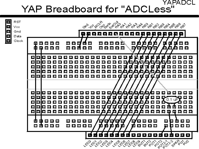
Using a breadboard, the experiment is wired using the guide:

If the EMU-II or YAP-II is used, the experiment is wired as:
The source code listed below can be accessed from the CD-ROM by clicking Here.
 title  "ADCLess - Reading a Resistor Value without an ADC"
;
;  This Program copies the "RCTIME" instruction of the Parallax Stamp.
;  A resistor value is read repeatedly and displayed.
;
;  This program is a modification of PROG17.ASM
;
;  Hardware Notes:
;   PIC16F84 running at 4 MHz
;   Reset is tied directly to Vcc and PWRT is Enabled.
;   A 10K Pot along with a 0.1uF Cap and 100 Ohm Series Resistor on
;    PORTA.0
;   A 220 Ohm Resistor and LED is attached to all the PORTB.7:0
;
;  Application Updated: 99.12.26 for 4 MHz PIC16F84.
;
;  Myke Predko
;  96.06.02
;
  LIST R=DEC
 ifdef __16F84
  INCLUDE "p16f84.inc"
 else
 ifdef __16F877
  INCLUDE "p16f877.inc"
 endif

;  Registers

 ifdef __16F84
 __CONFIG _CP_OFF & _WDT_OFF & _XT_OSC & _PWRTE_ON
 else
 __CONFIG _CP_OFF & _WDT_OFF & _XT_OSC & _PWRTE_ON & _DEBUG_OFF & _LVP_OFF & _BODEN_OFF
 endif

  PAGE
;  Mainline of ADCLess

 org     0

  nop

  movlw  0x0FF
  movwf  PORTB                  ;  Turn off all the LED's
  clrf   PORTA                  ;  Use PORTA as the Input

  bsf    STATUS, RP0            ;  Have to go to Page 0 to set Port Direction
  clrf   TRISB & 0x07F          ;  Set all the PORTB bits to Output
  movlw  0x0D2                  ;  Setup the Timer to fast count
  movwf  OPTION_REG & 0x07F	  ;   Put in Divide by 8 Prescaler for 4x
  ;   Clock
  bcf    STATUS, RP0            ;  Go back to Page 0

  movlw  TRISA                  ;  Have to Set/Read PORTA.0
  movwf  FSR			  ;   - Use FSR instead of Changing RP0

Loop

  bsf    PORTA, 0               ;  Charge Cap on PORTA.0
  bcf    INDF, 0                ;  Make PORTA.0 an Output
  movlw  0x0100 - 10		  ;  Charge the Cap
  clrf   TMR0                   ;  Now, Wait for the Cap to Charge
Sub_Loop1                       ;  Wait for the Timer to Reach 10
  movf   TMR0, w                ;  Get the Timer Value
  btfss  STATUS, Z              ;  Has the Timer Overflowed?
   goto  Sub_Loop1              ;   No, Loop Around again

  bsf    INDF, 0                ;  Now, Wait for the Cap to Discharge
  clrf   TMR0                   ;   and Time it.
Sub_Loop2                       ;  Just wait for PORTA.1 to go Low
  btfsc  PORTA, 0
   goto  Sub_Loop2

  comf   TMR0, w                ;  Get the Timer Value
  movwf  PORTB

  goto   Loop                   ;  Get another Time Sample


  end