- FirstAp
- RegAddr
- Status
- Arith
- MidGoto
- LowGoto
- CondJump
- VarMani
- VarArray
- StackOps
- FirstCal
- StakCall
- CallBUp
- Table0
- ArbTable
- SmallTbl
- StateMC
- LEDOn
- Current Consumption Check
- Debounce
- PinChg
- TimeEnd
- Decouple
- WDT
- PowerUp
- Reset
- TMR0
- Random
- Sleep
- DiffOsc
- EEPROM
- SHORT
- ADCLess
- ADC
- VLadder
- PWMOut
- Cylon
- TMR0Int
- LEDPWM
- IntDeb
- TrueRS
- BasicRS
- SimpRS
- 3RS
- Debug
Useful Code Snippets and Macros

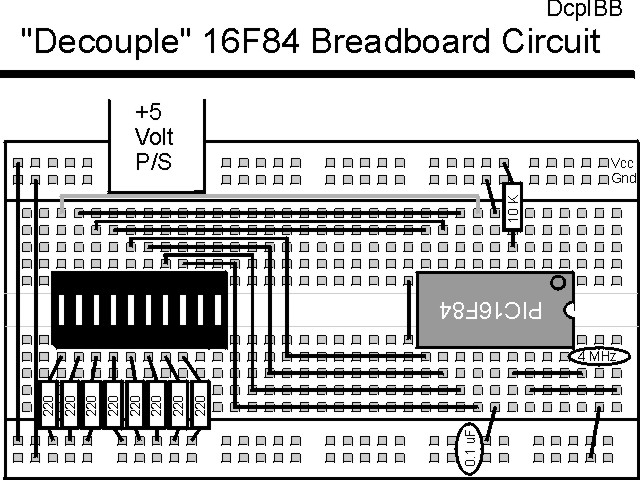
"Decouple" Experiment
Many people are unsure as to the need for decoupling capacitors in circuits. In this experiment, you will have a chance to see how decoupling capacitors can prevent inadvertant resets in the PICmicro, when it is switching large loads on and off. I have found this experiment to work best with a PIC16C84 and least well with a forty pin device like the PIC16F877.
The experiment uses the circuit shown below:

The parts needed for this experiment are listed in the table:
| Part | Description | Required for the YAP-II/EMU-II? |
|---|---|---|
| PICmicro® MCU | PIC16C84-04/P PIC16F84-04/P PIC16F877-04/P |
In Socket |
| Vdd/Vss Decoupling Capacitor | 0.1 uF (Any Type) | No |
| _MCLR Pull Up Resistor | 10K, 1/4 Watt | No |
| 4 MHz Ceramic Resonator | Three Leaded Ceramic Resonator with Built in 27-33pF Capacitors | No |
| PORTB LED Current Limiting Resistors | 8x 220W, 1/4 Watt | No - "LED1" Used |
| PORTB LED | 10 LED "Bargraph" Recommended | No - "LED1" through "LED9" Used |
| Breadboard | Any Type | No |
| +5 Volt "Vcc" Power Supply | Any Type | No |
Using a breadboard, the experiment is wired using the guide shown below. Note that this circuit will be used for some of the following applications, so you might not want to disconnect it after you are finished with it.
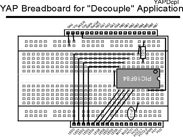
If the EMU-II or YAP-II is used, the PICmicro® MCU should be pulled out of the socket and placed on the motherboard as shown below. If the EMU-II is used, then a separate Ceramic Resonator will be required to run the application.
The source code listed below can be accessed from the CD-ROM by clicking Here.
 title  "Decouple - Decoupling Effects on a PICmicro's Operation"
#define nDebug
;
;  This Code "Hammers" a PICmicro's PortB with Changing Values
;   to investigate the effects of a Decoupling Capacitor
;
;
;  Hardware Notes:
;   PIC16F84 Running at 4 MHz
;   _MCLR is Pulled Up
;   All 8 bits of PortB are Pulled up and Connected to LEDs
;
;  Myke Predko
;  99.12.22
;
  LIST R=DEC
  INCLUDE "p16f84.inc"

;  Register Usage
 CBLOCK 0x020                   ;  Start Registers at End of the SFRs
Dlay:2
BValue
 ENDC


 PAGE
 __CONFIG _CP_OFF & _XT_OSC & _PWRTE_ON  & _WDT_OFF
                                ;  Note that the WatchDog Timer is OFF

;  Mainline of Decouple
  org    0

  movlw  0x0FF
  movwf  PORTB
  movwf  BValue

  bsf    STATUS, RP0		;  Make All 8 PortB Bits Output
  clrf   TRISB ^ 0x080
  bcf    STATUS, RP0

Loop				;  Loop Here

  call	 Delay

  bcf    STATUS, C		;  Change PORTB
  btfss  BValue, 7
   bsf   STATUS, C
  rlf    BValue, w
  movwf  PORTB
  movwf  BValue

  call   Delay

  movlw  0x0FF			;  Turn OFF LEDs
  movwf  PORTB

  goto   Loop

Delay				;  Delay 1/5 Seconds
  clrf   Dlay
  clrf   Dlay + 1
 ifndef Debug
  decfsz Dlay, f
   goto  $ - 1
  decfsz Dlay + 1, f
   goto  $ - 3
 else
  nop
  nop
  nop
  nop
 endif

  return


  end
Note that to produce a "quick and dirty" 1/5 of a second (200 msec) delay when the PICmicro is running at 4 MHz, I use the code:
Delay				;  Delay 1/5 Seconds
  clrf   Dlay
  clrf   Dlay + 1
 ifndef Debug
  decfsz Dlay, f
   goto  $ - 1
  decfsz Dlay + 1, f
   goto  $ - 3
 else
  nop
  nop
  nop
  nop
 endif
This delay also includes the use of the "Debug" #define which is used to
select whether or not the full delay executes in the simulator. If the statement
#define Debug is at the start of the application, then the delay will "fall
through" with a total delay of six instruction cycles.
As the code executes, pull the decoupling capacitor from the circuit. What you should see is the LED lighting procession stopping after a few cycles. This is caused by the current draw for the LEDs causing the voltage level inside the chip changing to the point where the PICmicro® MCU is unable to keep executing. When this happens, the chip resets and starts over.