- FirstAp
- RegAddr
- Status
- Arith
- MidGoto
- LowGoto
- CondJump
- VarMani
- VarArray
- StackOps
- FirstCal
- StakCall
- CallBUp
- Table0
- ArbTable
- SmallTbl
- StateMC
- LEDOn
- Current Consumption Check
- Debounce
- PinChg
- TimeEnd
- Decouple
- WDT
- PowerUp
- Reset
- TMR0
- Random
- Sleep
- DiffOsc
- EEPROM
- SHORT
- ADCLess
- ADC
- VLadder
- PWMOut
- Cylon
- TMR0Int
- LEDPWM
- IntDeb
- TrueRS
- BasicRS
- SimpRS
- 3RS
- Debug
Useful Code Snippets and Macros

"ADC" Experiment
The most practical method of reading using an ADC built into a PICmicro® MCU. In this experiment, I have repeated the previous (ADCLess) experiment but I use the built in ADC of a PIC16C711 instead of the characteristics of the digital I/O pins.
The ADC read can be carried out in the following macro:
ADCRead Macro
  bsf    ADCON0, GO		  ;  Turn on the ADC
  btfsc  ADCON0, GO		  ;  Wait for it to Complete
   goto  $ - 1
 endm
The experiment uses the circuit shown below:
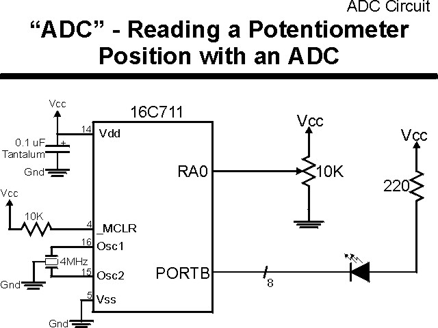
The parts needed for this experiment are listed in the table:
| Part | Description | Required for the YAP-II/EMU-II? |
|---|---|---|
| PICmicro® MCU | PIC16C711-JW PIC16F877-04/P |
In Socket |
| Vdd/Vss Decoupling Capacitor | 0.1 uF (Any Type) | No |
| _MCLR Pull Up Resistor | 10K, 1/4 Watt | No |
| 4 MHz Ceramic Resonator | Three Leaded Ceramic Resonator with Built in 27-33pF Capacitors | No |
| RA0 Potentiometer | 10K | No - "Pot1" Used |
| PORTB LED Current Limiting Resistors | 8x 220W, 1/4 Watt | No - "LED1" Used |
| PORTB LED | 10 LED "Bargraph" Recommended | No - "LED1" through "LED9" Used |
| Breadboard | Any Type | No |
| +5 Volt "Vcc" Power Supply | Any Type | No |
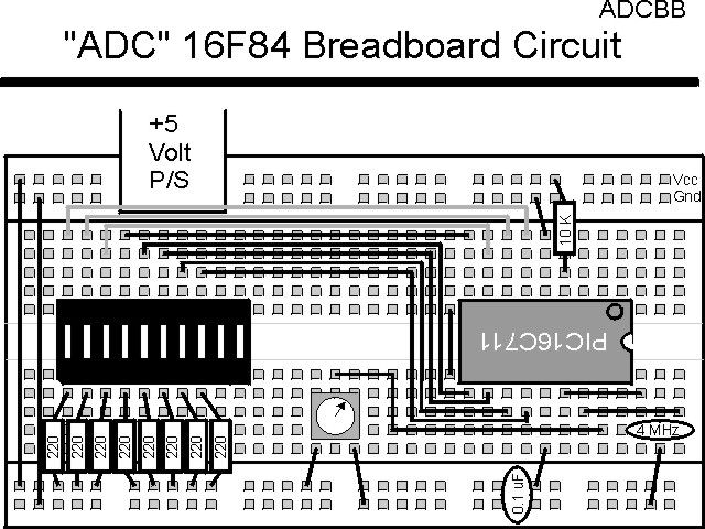
Using a breadboard, the experiment is wired using the guide:
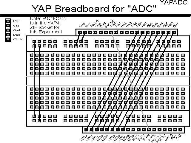
If the EMU-II or YAP-II is used, the experiment is wired as:
The source code listed below can be accessed from the CD-ROM by clicking Here.
 title  "ADC - Reading a Resistor Value with an ADC"
;
;  This Program Uses the ADC built into a PIC16C711 and
;  Reads an ADC Value and displays it on eight LEDs.
;
;  Hardware Notes:
;   PIC16C711 running at 4 MHz
;   Reset is tied directly to Vcc and PWRT is Enabled.
;   A 10K Pot Wired as a Voltage Divider on PORTA.0
;   A 220 Ohm Resistor and LED is attached to all the PORTB.7:0
;
;  Myke Predko
;  99.12.27
;
  LIST R=DEC
 ifdef __16C711
  INCLUDE "p16c711.inc"		  ;  <-- Note PIC16C711 Used
 else
 ifdef __16C877
  INCLUDE "p16f877.inc"
 endif
 endif

;  Registers

 ifdef __16C711
 __CONFIG _CP_OFF & _WDT_OFF & _XT_OSC & _PWRTE_ON
 else
 __CONFIG _CP_OFF & _WDT_OFF & _XT_OSC & _PWRTE_ON & _DEBUG_OFF & _LVP_OFF & _BODEN_OFF
 endif

  PAGE
;  Mainline of ADC

 org     0

  nop

  movlw  0x0FF
  movwf  PORTB                  ;  Turn off all the LED's
  clrf   PORTA                  ;  Use PORTA as the Input

  bsf    STATUS, RP0
  clrf   TRISB & 0x07F          ;  Set all the PORTB bits to Output
 ifdef __16C711			  ;  Make Sure all ADC Bits are Output
  clrf   ADCON1 ^ 0x080		  ;  Make RA0 to RA3 ADC input
 else
  movlw  B'00000000'		  ;  For 16F877, Make 10 Bit ADC "Left
  movwf  ADCON1 ^ 0x080		  ;   Justified"
 endif
  bcf    STATUS, RP0            ;  Go back to Page 0

  movlw  0x081  			  ;  Setup ADCON0 for ADC Conversion
  movwf  ADCON0			  ;   ADCS1:ADCS0 - 10 for /32 Clock
				  ;   Unimplemented - 0
		 			  ;   CHS1:CHS0 - 00 for RA0/AN0
				  ;   Go/_Done - 0
					  ;   ADIF - 0
					  ;   ADON - 1

Loop

  movlw  3				  ;  Wait 12 usec for ADC to Charge
  addlw  0x0FF			  ;  Take One Away to Setup the Charge
  btfss  STATUS, Z
   goto  $ - 2

  bsf    ADCON0, GO		  ;  Turn on the ADC
  btfsc  ADCON0, GO		  ;  Wait for it to Complete
   goto  $ - 1

  bsf    STATUS, RP0
 ifdef __16C711
  comf   ADRES, w               ;  Get the Timer Value
 else
  comf   ADRESH, w		  ;  Read Most Significant 8 Bits in
 endif				  ;   PIC16F877
  bcf    STATUS, RP0
  movwf  PORTB

  goto   Loop                   ;  Get another Time Sample


  end