- FirstAp
- RegAddr
- Status
- Arith
- MidGoto
- LowGoto
- CondJump
- VarMani
- VarArray
- StackOps
- FirstCal
- StakCall
- CallBUp
- Table0
- ArbTable
- SmallTbl
- StateMC
- LEDOn
- Current Consumption Check
- Debounce
- PinChg
- TimeEnd
- Decouple
- WDT
- PowerUp
- Reset
- TMR0
- Random
- Sleep
- DiffOsc
- EEPROM
- SHORT
- ADCLess
- ADC
- VLadder
- PWMOut
- Cylon
- TMR0Int
- LEDPWM
- IntDeb
- TrueRS
- BasicRS
- SimpRS
- 3RS
- Debug
Useful Code Snippets and Macros

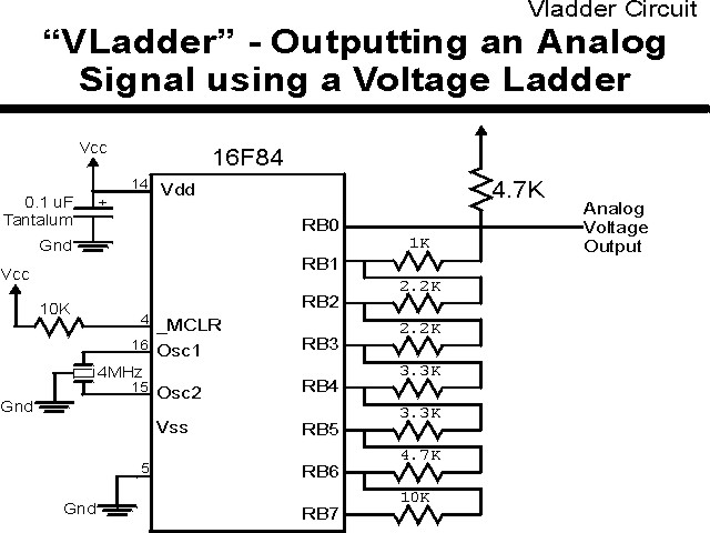
"VLadder" Experiment
Driving out analog voltages from the PICmicro is not a trivial task. In this and the next experiment, I present some ways of implementing the function. Both methods can only supply a low amount of current - for high current loads (more than 1 mA), a voltage following buffer will have to be used to output the analog voltages at higer currents.
For this experiment, I have created a "Resistor Laddering" useing the circuit
shown below:
The parts needed for this experiment are listed in the table:
| Part | Description | Required for the YAP-II/EMU-II? |
|---|---|---|
| PICmicro® MCU | PIC16F84-04/P PIC16F877-04/P |
In Socket |
| Vdd/Vss Decoupling Capacitor | 0.1 uF (Any Type) | No |
| _MCLR Pull Up Resistor | 10K, 1/4 Watt | No |
| 4 MHz Ceramic Resonator | Three Leaded Ceramic Resonator with Built in 27-33pF Capacitors | No |
| 10K 1/4 Watt resistor | Any Type | Yes |
| 4.7K, 1/4 Watt resistors | 2x Any Type | Yes |
| 2.2K, 1/4 Watt resistors | 2x Any Type | Yes |
| 3.3K, 1/4 Watt resistors | 2x Any Type | Yes |
| 1K 1/4 Watt resistor | Any Type | Yes |
| Breadboard | Any Type | No |
| +5 Volt "Vcc" Power Supply | Any Type | No |
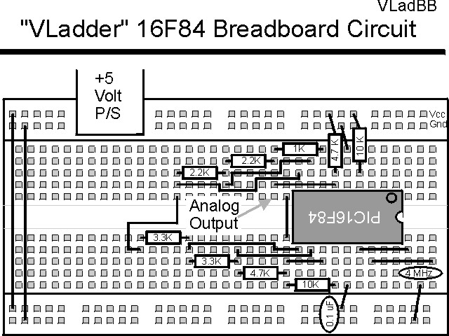
Using a breadboard, the experiment is wired using the guide:
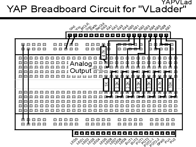
If the EMU-II or YAP-II is used, the experiment is wired as:
The source code listed below can be accessed from the CD-ROM by clicking Here.
 title  "VLadder - Resistor Ladder Analog Output."
#define DMM
;
;  This Program Runs through a Saw Tooth Analog Output from the
;  16C84.  The Output is generated by a Resistor Ladder attached
;  to PORTB.  To set a particular voltage, a bit is output to 0 volts.
;
;  Hardware Notes:
;   PIC16F84 Running at 4 MHz
;   Reset is tied directly to Vcc and PWRT is Enabled.
;   The Resistor Ladder is attached to PORTB.7:0
;
;   A 4.7K Resistor between PORTB.0 and Vcc (Output is taken from here
;    as well)
;   A 1K Resistor between PORTB.0 and PORTB.1
;   A 2.2K Resistor between PORTB.1 and PORTB.2
;   A 2.2K Resistor between PORTB.2 and PORTB.3
;   A 3.3K Resistor between PORTB.3 and PORTB.4
;   A 3.3K Resistor between PORTB.4 and PORTB.5
;   A 4.7K Resistor between PORTB.5 and PORTB.6
;   A 10K Resistor between PORTB.6 and PORTB.7
;
;  Updated: 99.12.27 - For Second Edition
;
;  Myke Predko
;  96.06.27
;
  LIST R=DEC
 ifdef __16F84
  INCLUDE "p16f84.inc"
 else
 ifdef __16F877
  INCLUDE “p16f877.inc”
 endif

;  Registers
 CBLOCK 0x020
Count, Counthi, Countu
 ENDC

 ifdef __16F84
 __CONFIG _CP_OFF & _WDT_OFF & _XT_OSC & _PWRTE_ON
 else
 __CONFIG _CP_OFF & _WDT_OFF & _XT_OSC & _PWRTE_ON & _DEBUG_OFF & _LVP_OFF & _BODEN_OFF
 endif

  PAGE
;  Code for VLadder

  org    0

  nop

  clrf   PORTB

  movlw  TRISB                  ;  Setup the TRIS Values
  movwf  FSR

  bcf    STATUS, C              ;  Use the Carry as the Skip Value

Loop                            ;  Loop Around Here to Output Sawtooth

 ifdef   DMM                    ;  Just Dlay if only a DMM Available
  call   Delay                  ;   for Seeing the Output
 endif

  rlf    INDF, f

  goto   Loop


 ifdef   DMM
Delay

  clrf   Count			;  Display for one Second
  clrf   Counthi
  movlw  6
  movwf  Countu
Dlay
  decfsz Count, f
   goto  Dlay
  decfsz Counthi, f
   goto  Dlay
  decfsz Countu, f
   goto  Dlay

  return
 endif


 end