- FirstAp
- RegAddr
- Status
- Arith
- MidGoto
- LowGoto
- CondJump
- VarMani
- VarArray
- StackOps
- FirstCal
- StakCall
- CallBUp
- Table0
- ArbTable
- SmallTbl
- StateMC
- LEDOn
- Current Consumption Check
- Debounce
- PinChg
- TimeEnd
- Decouple
- WDT
- PowerUp
- Reset
- TMR0
- Random
- Sleep
- DiffOsc
- EEPROM
- SHORT
- ADCLess
- ADC
- VLadder
- PWMOut
- Cylon
- TMR0Int
- LEDPWM
- IntDeb
- TrueRS
- BasicRS
- SimpRS
- 3RS
- Debug
Useful Code Snippets and Macros

"TMR0Int" Experiment
I always like looking at something from a different perspective. The genesis of this experiment was a question that was asked on the PICList; could you set up TMR0 so that the next detected edge causes an interrupt? The answer to that is yes, and it is demonstrated in this experiment.
By using the code in this experiment, you can add another interrupt source to your mid-range PICmicro® MCU application, or use it to capture events in a low-end application. Using this application to capture events in the low-end PICmicro MCU gives it the ability to "record" pulses or behave like a simple interrupt request generator (when TMR0 is equal to zero, then execute the response handler).
This experiment uses the circuit shown below:
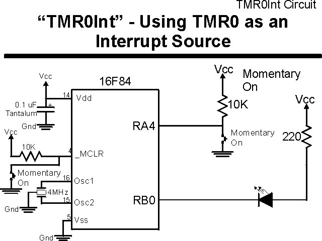
The parts needed for this experiment are listed in the table:
| Part | Description | Required for the YAP-II/EMU-II? |
|---|---|---|
| PICmicro® MCU | PIC16F84-04/P PIC16F877-04/P |
In Socket |
| Vdd/Vss Decoupling Capacitor | 0.1 uF (Any Type) | No |
| _MCLR Pull Up Resistor | 10K, 1/4 Watt | No |
| 4 MHz Ceramic Resonator | Three Leaded Ceramic Resonator with Built in 27-33pF Capacitors | No |
| RA4 Pull Up | 10K, 1/4 Watt | No - "BUT1" Used |
| RA4 Push Button | Momentary On/Modified for Breadboard | No - "BUT1" Used |
| PORTB LED Current Limiting Resistors | 8x 220W, 1/4 Watt | No - "LED1" Used |
| PORTB LED | 10 LED "Bargraph" Recommended | No - "LED1" through "LED9" Used |
| Breadboard | Any Type | No |
| +5 Volt "Vcc" Power Supply | Any Type | No |
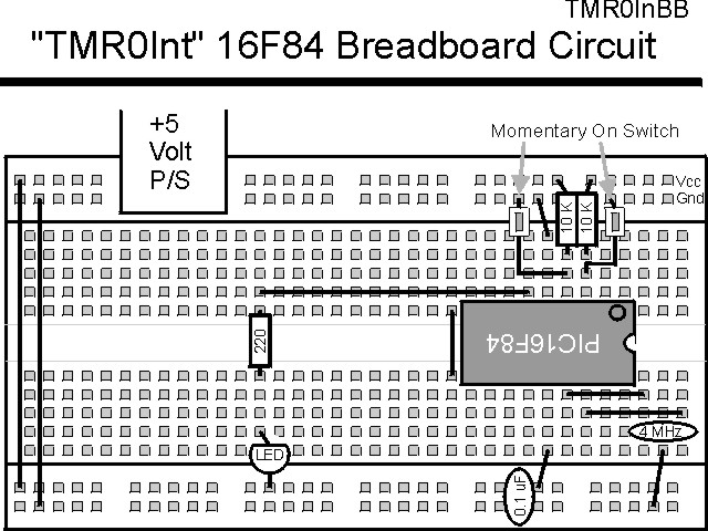
Using a breadboard, the experiment is wired using the guide:
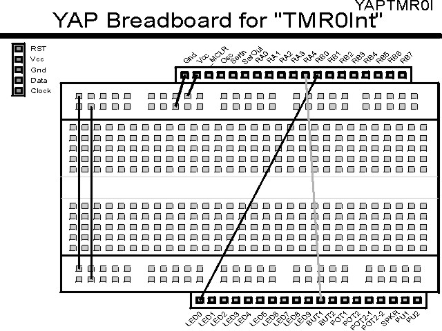
If the EMU-II or YAP-II is used, the experiment is wired as:
The source code listed below can be accessed from the CD-ROM by clicking Here.
 title  "TMR0Int - Treat TMR0 Input like an Interrupt Input"
;
;  This Application uses the TMR0 Input Pin (RA4 in the mid-range
;   PICmicros) as an interrupt source.  When the input data changes,
;   TMR0 overflows, which causes an interrupt request.
;
;  Hardware Notes:
;   This application runs on a PIC16F84 executing at 4 MHz
;   _MCLR is tied through a 10K Resistor to Vcc and PWRT is Enabled
;   A 10K Pull-Up and a Momentary "On" Switch is Connected to RA4
;   A 220 Ohm Resistor and LED is connected between PORTB.0 and Vcc
;
;  Myke Predko
;  99.12.28
;
  LIST R=DEC
 ifdef __16F84
  INCLUDE "p16f84.inc"
 else
 ifdef __16F877
  INCLUDE "p16f877.inc"
 endif

;  Registers
 CBLOCK 0x020
_w, _status			;  Context Register Save Values
 ENDC


 ifdef __16F84
 __CONFIG _CP_OFF & _WDT_OFF & _XT_OSC & _PWRTE_ON
 else
 __CONFIG _CP_OFF & _WDT_OFF & _XT_OSC & _PWRTE_ON & _DEBUG_OFF & _LVP_OFF & _BODEN_OFF
 endif

  PAGE
;  Mainline of cylon

 org     0

  nop

  movlw  0x0FF
  movwf  PORTB

  goto   Mainline

 org     4
Int				;  TMR0 has Overflowed - New Input

  bcf    INTCON, T0IF	;  Reset the Interrupt Flag

  bcf    PORTB, 0		;  Turn on the LED

  retfie

Mainline			;  Setup TMR0 Interrupt

  bsf    STATUS, RP0    ;  Goto Bank 1 to set Port Direction
  bcf    PORTB, 0		;  Enable RB0 for Output
  bcf    STATUS, RP0    ;  Go back to Bank 0

  movlw  OPTION_REG	;  Point to the Option Register
  movwf  FSR

  clrf   TMR0		;  Reset the Timer

  movlw  (1 << GIE) | (1 << T0IE)
  movwf  INTCON		;  Enable Interrupts

  movlw  0x0C0		;  Make TMR0 Driven by the Instruction Clock
  movwf  INDF

  movlw  0x0FF
  movwf  TMR0

  bsf    INDF, T0CS	;  Now, Make TMR0 Driven Externally

Loop				;  Loop Here

  goto   Loop		;  Let Interrupt Handler Work in the Background


 end