- FirstAp
- RegAddr
- Status
- Arith
- MidGoto
- LowGoto
- CondJump
- VarMani
- VarArray
- StackOps
- FirstCal
- StakCall
- CallBUp
- Table0
- ArbTable
- SmallTbl
- StateMC
- LEDOn
- Current Consumption Check
- Debounce
- PinChg
- TimeEnd
- Decouple
- WDT
- PowerUp
- Reset
- TMR0
- Random
- Sleep
- DiffOsc
- EEPROM
- SHORT
- ADCLess
- ADC
- VLadder
- PWMOut
- Cylon
- TMR0Int
- LEDPWM
- IntDeb
- TrueRS
- BasicRS
- SimpRS
- 3RS
- Debug
Useful Code Snippets and Macros

"Debug" Experiment
For the last experiment, you can try to get this application working. You should expect the LED connected to RB1 to light and the LED connected to RB0 to light when the button is pressed. The next page gives the solution to the problems in this application. The circuit is:
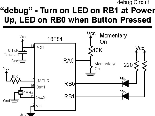
The parts needed for this experiment are listed in the table:
| Part | Description |
|---|---|
| PICmicro® MCU | PIC16F84-04/P |
| Vdd/Vss Decoupling Capacitor | 0.1 uF (Any Type) |
| _MCLR Pull Up Resistor | 10K, 1/4 Watt |
| 4 MHz Ceramic Resonator | Three Leaded Ceramic Resonator with Built in 27-33pF Capacitors |
| RA0 Pull Up | 10K, 1/4 Watt |
| RA0 Push Button | Momentary On/Modified for Breadboard |
| RB0 LED Current Limiting Resistor | 220W, 1/4 Watt |
| RB0 LED | Any Type |
| RB1 LED Current Limiting Resistor | 220W, 1/4 Watt |
| RB1 LED | Any Type |
| Breadboard | Any Type |
| +5 Volt "Vcc" Power Supply | Any Type |
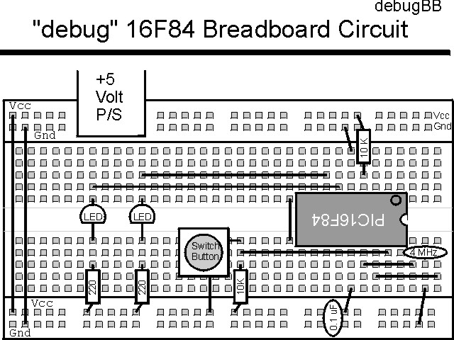
Using a breadboard, the experiment is wired using the guide:
The source code listed below can be accessed from the CD-ROM by clicking Here.
 title  "debug - An application with a few problems"
;
;  This is an application to demonstrate how insidious some problems
;   can be.  This application should be burned into a PICmicro after
;   assembly to see if the problems built into it can be found.
;
;  The application is *supposed* to turn on a LED at RB1 and wait for
;   a button to be pressed.  When it is, an LED at RB0 should be turned
;   on as well.
;
;  Hardware Notes:
;   PIC16F84 running at 4 MHz
;   _MCLR is tied through a 4.7K Resistor to Vcc and PWRT is Enabled
;   A 220 Ohm Resistor and LED is attached to PORTB.0/PORTB.1 and Vcc
;   A 10K pull up is connected to RA0 with a Momentary on Switch
;
;  Myke Predko
;  99.12.07
;
  LIST R=DEC
  INCLUDE "p16f84.inc"

;  Registers

 __CONFIG _CP_OFF & _WDT_ON & _XT_OSC & _PWRTE_ON

  PAGE
;  Mainline of debug

 org     0

  nop

  movlw  0x001			;  LED at RB1 is On/RB0 is Off
  movwf  PORTB

  bsf    STATUS, RP0          ;  Goto Bank 1 to set Port Direction
  movlw  0x0FC			;  Set RB0/RB1 to Output
  movwf  TRISB ^ 0x090
  bcf    STATUS, RP0          ;  Go back to Bank 0

Loop
  btfsc  PORTA, 0			;  Wait for RA0 Button to be Pressed
   goto  Loop

  clrf   PORTA			;  Set RB0 = RB1 = 0 for Both LEDs on

  goto   Loop			;  Loop Forever


 end
You will find that this experiment does not work as I outlined above. There are a number of problems - see if you can find them.
Click Here to look at the corrections to the problems in this experiment.