- FirstAp
- RegAddr
- Status
- Arith
- MidGoto
- LowGoto
- CondJump
- VarMani
- VarArray
- StackOps
- FirstCal
- StakCall
- CallBUp
- Table0
- ArbTable
- SmallTbl
- StateMC
- LEDOn
- Current Consumption Check
- Debounce
- PinChg
- TimeEnd
- Decouple
- WDT
- PowerUp
- Reset
- TMR0
- Random
- Sleep
- DiffOsc
- EEPROM
- SHORT
- ADCLess
- ADC
- VLadder
- PWMOut
- Cylon
- TMR0Int
- LEDPWM
- IntDeb
- TrueRS
- BasicRS
- SimpRS
- 3RS
- Debug
Useful Code Snippets and Macros

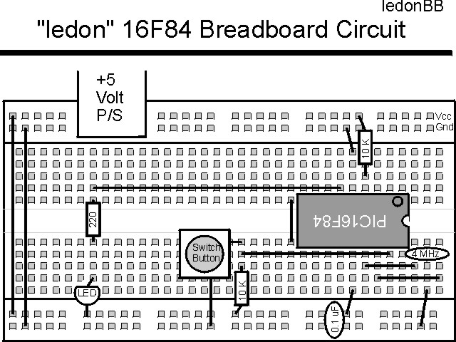
"LEDOn" Experiment
This is the first experiment where a PICmicro® MCU is actually programmed and run. This experiment simply waits for a button to be pressed and turns on an LED. The circuit is:

The parts needed for this experiment are listed in the table:
| Part | Description | Required for the YAP-II/EMU-II? |
|---|---|---|
| PICmicro® MCU | PIC16F84-04/P PIC16F877-04/P |
In Socket |
| Vdd/Vss Decoupling Capacitor | 0.1 uF (Any Type) | No |
| _MCLR Pull Up Resistor | 10K, 1/4 Watt | No |
| 4 MHz Ceramic Resonator | Three Leaded Ceramic Resonator with Built in 27-33pF Capacitors | No |
| RA0 Pull Up | 10K, 1/4 Watt | No - "BUT1" Used |
| RA0 Push Button | Momentary On/Modified for Breadboard | No - "BUT1" Used |
| RB0 LED Current Limiting Resistor | 220W, 1/4 Watt | No - "LED1" Used |
| RB0 LED | Any Type | No - "LED1" Used |
| Breadboard | Any Type | No |
| +5 Volt "Vcc" Power Supply | Any Type | No |
Using a breadboard, the experiment is wired using the guide:
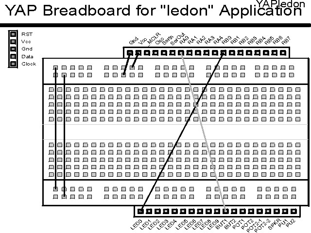
If the EMU-II or YAP-II is used, the experiment is wired as:
The experiment can be modeled as the "C" source application:
main()				//  "LEDOn" Experiment
{

  PORTB.0 = High;			//  Make RB0 High so LED is Off
  TRISB.0 = Output;		//  Make RB0 Output for LED Driving

  while (1 == 1)			//  Loop Forever
    PORTB.0 = PORTA.0;

}  //  end LEDOn
The source code listed below can be accessed from the CD-ROM by clicking Here.
 title  "ledon - Turn on a LED when a Button is Pressed"
;
;  This is the First Program to be Burned in and Run in a PIC.
;
;  The Program simply sets up Bit 0 of Port "A" to Output and then
;   Sets it Low when RA0 is pulled low.
;
;  Hardware Notes:
;   _MCLR is tied through a 4.7K Resistor to Vcc and PWRT is Enabled
;   A 220 Ohm Resistor and LED is attached to PORTB.0 and Vcc
;   A 10K pull up is connected to RA0 and it's state is passed to
;    RB0
;
;  Myke Predko
;  99.12.03
;
  LIST R=DEC
 ifdef __16F84
  INCLUDE "p16f84.inc"
 else
 ifdef __16F877
  INCLUDE "p16f877.inc"
 endif

;  Registers

 ifdef __16F84
 __CONFIG _CP_OFF & _WDT_OFF & _XT_OSC & _PWRTE_ON
 else
 __CONFIG _CP_OFF & _WDT_OFF & _XT_OSC & _PWRTE_ON & _DEBUG_OFF & _LVP_OFF & _BODEN_OFF
 endif

  PAGE
;  Mainline of ledon

 org     0

  nop					  ;  "nop" is Required for Emulators

  bsf    PORTB, 0               ;  Make the LED on PORTB.0 "off"

  bsf    STATUS, RP0            ;  Goto Bank 1 to set Port Direction
  bcf    TRISB ^ 0x080, 0       ;  Set RB0 to Output
  bcf    STATUS, RP0            ;  Go back to Bank 0

Loop
  movf   PORTA, w			  ;  Simply Transfer PORTA.0 to PORTB.0
  movwf  PORTB

  goto   Loop


 end
Click Here to look at the nineteenth experiment - Current Consumption Check