- FirstAp
- RegAddr
- Status
- Arith
- MidGoto
- LowGoto
- CondJump
- VarMani
- VarArray
- StackOps
- FirstCal
- StakCall
- CallBUp
- Table0
- ArbTable
- SmallTbl
- StateMC
- LEDOn
- Current Consumption Check
- Debounce
- PinChg
- TimeEnd
- Decouple
- WDT
- PowerUp
- Reset
- TMR0
- Random
- Sleep
- DiffOsc
- EEPROM
- SHORT
- ADCLess
- ADC
- VLadder
- PWMOut
- Cylon
- TMR0Int
- LEDPWM
- IntDeb
- TrueRS
- BasicRS
- SimpRS
- 3RS
- Debug
Useful Code Snippets and Macros

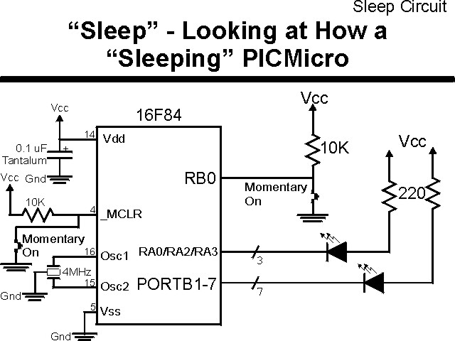
"Sleep" Experiment
"Sleep" is an interesting feature of the PICmicro® MCU; it can be used to halt the processor in an application where it is no longer needed ("Sleep" is implemented as "End" in PicBasic) or it can be used to halt the PICmicro MCU until the user requires it again. This experiment looks at the PICmicro MCU's "sleep" instruction and operation as well as how it can be used to resume the application.
The experiment uses the circuit shown below:
The parts needed for this experiment are listed in the table:
| Part | Description | Required for the YAP-II/EMU-II? |
|---|---|---|
| PICmicro® MCU | PIC16F84-04/P PIC16F877-04/P |
In Socket |
| Vdd/Vss Decoupling Capacitor | 0.1 uF (Any Type) | No |
| _MCLR Pull Up Resistor | 10K, 1/4 Watt | No |
| 4 MHz Ceramic Resonator | Three Leaded Ceramic Resonator with Built in 27-33pF Capacitors | No |
| RB0 Pull Up | 10K, 1/4 Watt | No - "BUT1" Used |
| RB0 Push Button | Momentary On/Modified for Breadboard | No - "BUT1" Used |
| PORTA/PORTB LED Current Limiting Resistors | 10x 220W, 1/4 Watt | No - "LED1" Used |
| PORTA/PORTB LED | 10 LED "Bargraph" Recommended | No - "LED1" through "LED9" Used |
| Breadboard | Any Type | No |
| +5 Volt "Vcc" Power Supply | Any Type | No |
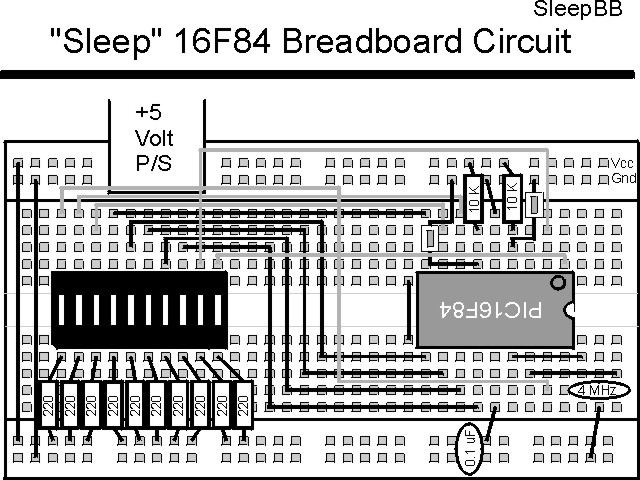
Using a breadboard, the experiment is wired using the guide:
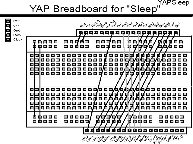
If the EMU-II or YAP-II is used, the experiment is wired as:
The source code listed below can be accessed from the CD-ROM by clicking Here.
 title  "Sleep - Demonstrate the PICmicro Modes of 'Sleep'"
;
;  This Application Displays a Counter on PORTB (if code is
;   set up) and shows the current "_TO" and "_PD" bits of the
;   STATUS Register.
;
;
;  Hardware Notes:
;   PIC16F84 Running at 4 MHz
;   _MCLR is Pulled Up with a Button on it
;   RB0 is Pulled up with a Momentary On Switch Pulling to Ground
;   All 7 remaining bits of PortB are Pulled up and Connected to LEDs
;   PORTA.0 is Pulled up and Connected to a LED for LSB of the Counter
;   PORTA.2 is Pulled up and Connected to a LED for _PD
;   PORTA.3 is Pulled up and Connected to a LED for _TO
;
;  Myke Predko
;  99.12.28
;
  LIST R=DEC
 ifdef __16F84
  INCLUDE "p16f84.inc"
 else
 ifdef __16F877
  INCLUDE "p16f877.inc"
 endif

;  Register Usage
 CBLOCK 0x020                 ;  Start Registers at End of the Values
Check:4				;  The Four Bytes of the Check
Counter				;  Count Value
 ENDC


 PAGE
 ifdef __16F84
 __CONFIG _CP_OFF & _WDT_OFF & _XT_OSC & _PWRTE_ON
 else
 __CONFIG _CP_OFF & _WDT_OFF & _XT_OSC & _PWRTE_ON & _DEBUG_OFF & _LVP_OFF & _BODEN_OFF
 endif
                              ;  Note that the WatchDog Timer is ON

;  Mainline of Sleep
  org    0
Loop					;  Loop Here Each Time Executes

  nop

  bsf    STATUS, RP0
  movlw  0x012			;  RA0, RA2 & RA3 are Outputs
  movwf  TRISA ^ 0x080
  movlw  0x01			;  RB1 to RB7 are Outputs
  movwf  TRISB ^ 0x080
  bcf    STATUS, RP0

  rrf    STATUS, w		;  Get the _TO/_PD Bits
  xorlw  0x0FF
  andlw  0x0FE			;  Make Sure LED at RA0 is Clear
  movwf  PORTA			;   Display on RA2/RA3

  movf   Check, w			;  Is this a Reset or First Time Through?
  xorlw  0x0FF
  btfss  STATUS, Z
   goto  FirstTime
  movf   Check + 1, w
  xorlw  0x000
  btfss  STATUS, Z
   goto  FirstTime
  movf   Check + 2, w
  xorlw  0x0AA
  btfss  STATUS, Z
   goto  FirstTime
  movf   Check + 3, w
  xorlw  0x055
  btfss  STATUS, Z
   goto  FirstTime

  incf   Counter, f

  comf   Counter, w		;  Output the Counter Value
  movwf  PORTB			;  Output the High Seven Bits
  andlw  1
  iorwf  PORTA, f			;  Output the Low Bit

  bsf    INTCON, INTE		;  Enable a Pin Interrupt

  sleep				;  Execute the Sleep Instruction
  nop

  clrwdt				;  Clear WDT To Reset 2.3 seconds later

  goto   Loop

FirstTime				;  Set up the Count to See Differences

  movlw  0x0FF
  movwf  Check
  movlw  0x000
  movwf  Check + 1
  movlw  0x0AA
  movwf  Check + 2
  movlw  0x055
  movwf  Check + 3

  movlw  0x00			;  Turn on all the LEDs
  movwf  PORTB
  bcf    PORTA, 0

  clrf   Counter			;  Reset the Counter

  bsf    INTCON, INTE		;  Allow Buttons to Reset

  sleep				;  Go to Sleep
  nop

  goto   Loop			;  Display the New Data


  end