- FirstAp
- RegAddr
- Status
- Arith
- MidGoto
- LowGoto
- CondJump
- VarMani
- VarArray
- StackOps
- FirstCal
- StakCall
- CallBUp
- Table0
- ArbTable
- SmallTbl
- StateMC
- LEDOn
- Current Consumption Check
- Debounce
- PinChg
- TimeEnd
- Decouple
- WDT
- PowerUp
- Reset
- TMR0
- Random
- Sleep
- DiffOsc
- EEPROM
- SHORT
- ADCLess
- ADC
- VLadder
- PWMOut
- Cylon
- TMR0Int
- LEDPWM
- IntDeb
- TrueRS
- BasicRS
- SimpRS
- 3RS
- Debug
Useful Code Snippets and Macros

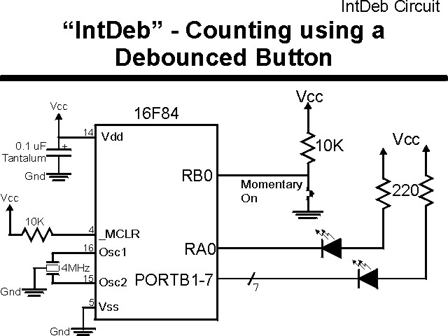
"IntDeb" Experiment
This experiment is a repeat of "Debounce" except that the input button is debounced using interrupts (with TMR0 as a source) instead of polling a pin. The code used in this experiment is useful for implementing "background" polls of a button and respond in the application when the ButUp or ButDown flag is set.
This experiment uses the circuit shown below:
The parts needed for this experiment are listed in the table:
| Part | Description | Required for the YAP-II/EMU-II? |
|---|---|---|
| PICmicro® MCU | PIC16F84-04/P PIC16F877-04/P |
In Socket |
| Vdd/Vss Decoupling Capacitor | 0.1 uF (Any Type) | No |
| _MCLR Pull Up Resistor | 10K, 1/4 Watt | No |
| 4 MHz Ceramic Resonator | Three Leaded Ceramic Resonator with Built in 27-33pF Capacitors | No |
| RB0 Pull Up | 10K, 1/4 Watt | No - "BUT1" Used |
| RB0 Push Button | Momentary On/Modified for Breadboard | No - "BUT1" Used |
| RA0/PORTB LED Current Limiting Resistors | 8x 220W, 1/4 Watt | No - "LED1" through "LED9" Used |
| RA0/PORTB LED | 10 LED "Bargraph" display | No - "LED1" through "LED9" Used |
| Breadboard | Any Type | No |
| +5 Volt "Vcc" Power Supply | Any Type | No |
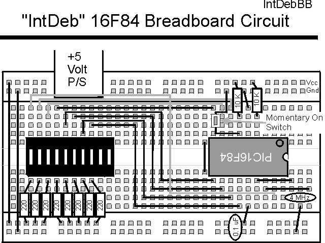
Using a breadboard, the experiment is wired using the guide:
If the EMU-II or YAP-II is used, the experiment is wired as:

The source code listed below can be accessed from the CD-ROM by clicking Here.
 title  "IntDeb - Register Contents Int Debounce."
#define nDebug
;
;  This is Program reads the value in a RAM Register and outputs it
;  inverted onto PORTB (which has LEDs to Display the Value).  All the
;  RAM Registers are Read and Displayed.  A button is used as the
;  instigator of the next value read.  The FSR is Copied into the LEDs
;  to Display the current Register Being Displayed.
;
;  This program is a modification of PROG18.ASM to use the Interrupt
;   Handler to Debounce the Button Input.
;
;  Hardware Notes:
;   Reset is tied directly to Vcc and PWRT is Enabled.
;   A 4.7K Pullup and Switch Pull-Down is attached to PORTB.0
;   A 220 Ohm Resistor and LED is attached to PORTB.7:1
;   A 220 Ohm Resistor and LED is attached to PORTA.0
;
;  Updated for the Second Edition: 99.12.28
;
;  Myke Predko
;  97.02.22
;
  LIST R=DEC
 ifdef __16F84
  INCLUDE "p16f84.inc"
 else
 ifdef __16F877
  INCLUDE "p16f877.inc"
 endif

;  Registers
 CBLOCK 0x020
Flags
Reg                 		;  Register to Display
 ENDC

#define ButUp   Flags, 0      ;  Flags Indicating Button State
#define ButDown Flags, 1


 ifdef __16F84
 __CONFIG _CP_OFF & _WDT_OFF & _XT_OSC & _PWRTE_ON
 else
 __CONFIG _CP_OFF & _WDT_OFF & _XT_OSC & _PWRTE_ON & _DEBUG_OFF & _LVP_OFF & _BODEN_OFF
 endif

  PAGE
;  Mainline of IntDeb

  org 0

  nop

  clrf   Flags                ;  No Button Pressed Yet
  clrf   Reg

  goto   MainLine

  org 4                       ;  Interrupt Handler Address
Int

  btfss  INTCON, T0IF         ;  Do we have a Timer Overflow?
   goto  Int_Switch           ;   No - Handle the Switch

  bcf    INTCON, T0IF         ;  Yes, Reset Timer Interrupt Request

  movlw  0x001			;  Assume the Button is Up
  btfss  PORTB, 0			;  Is the Button Up or Down?
   movlw 0x002			;   - If PORTB is Low, Button Down
  movwf  Flags

  goto   Int_End

Int_Switch                    ;  Interrupt on the Switch - Reset Timer

  bcf    INTCON, INTF         ;  Reset the Interrupt Request

  clrf   Flags			;  Indicate that Nothing is Valid

  movf   PORTB, 0			;  What is the Button State?
  andlw  1
  bsf    STATUS, RP0
  bcf    OPTION_REG ^ 0x080, INTEDG
  btfsc  STATUS, Z		;  Determine the Actual Edge
   bsf   OPTION_REG ^ 0x080, INTEDG
  bcf    STATUS, RP0

  clrf   TMR0                 ;  Going to Wait for another Key Press

Int_End

  retfie


 PAGE
MainLine                      ;  Mainline of reading the File Registers

  movlw  0x0FF
  movwf  PORTB                ;  Turn off all the Indicator LED's
  movwf  PORTA

  movf   PORTB, w
  andlw  1				;  Set 0 if Pin Down

  bsf    STATUS, RP0
  bcf    TRISA ^ 0x080, 0	;  RA0 is Output
  movlw  1				;  RB0 is Input/Interrupt
  movwf  TRISB ^ 0x080        ;  Set PORTB.7:1 bits to Output
 ifdef Debug
  movlw  0x090                ;  Zero Prescaler for TMR0 if Debug
  btfsc  STATUS, Z
   movlw 0x0D0			;  Pin down, Go for the Rising Edge
 else
  movlw  0x096                ;  Setup Prescaler for TMR0 to 32.7 msec
  btfsc  STATUS, Z
   movlw 0x0D6			;  Pin down, Go for the Rising Edge
 endif
  movwf  OPTION_REG ^ 0x080
  bcf    STATUS, RP0

  clrf   TMR0			;  Reset TMR0

  movlw  (1 << GIE) | (1 << T0IE) | (1 << INTE)
  movwf  INTCON			;  Setup the Interrupt Delays

Loop                          ;  Loop to Here for Each Register

  btfss  ButUp			;  Wait for the Button to be Debounced UP
   goto  $ - 1

  btfss  ButDown			;  Wait for Button be to Debounced Down
   goto  $ - 1

  incf   Reg, f               ;  Increment the Counter

  comf   Reg, w               ;  Display the Counter Value
  movwf  PORTB
  movwf  PORTA

  goto   Loop


 end