- FirstAp
- RegAddr
- Status
- Arith
- MidGoto
- LowGoto
- CondJump
- VarMani
- VarArray
- StackOps
- FirstCal
- StakCall
- CallBUp
- Table0
- ArbTable
- SmallTbl
- StateMC
- LEDOn
- Current Consumption Check
- Debounce
- PinChg
- TimeEnd
- Decouple
- WDT
- PowerUp
- Reset
- TMR0
- Random
- Sleep
- DiffOsc
- EEPROM
- SHORT
- ADCLess
- ADC
- VLadder
- PWMOut
- Cylon
- TMR0Int
- LEDPWM
- IntDeb
- TrueRS
- BasicRS
- SimpRS
- 3RS
- Debug
Useful Code Snippets and Macros

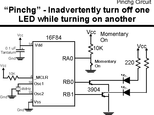
"PinChg" Experiment
It is important to remember that the :
bsf Register, Pin
instruction actually executes as:
Register = Register | (1 << Pin)
and the
bcf Register, Pin
instruction actually executes as:
Register = Register & (0x0FF ^ (1 << Pin))
If an output (or input) pin is held at an undesireable state when one
of these instructions is executed on another pin, then when the pin becomes an output,
you will find that the pin will be at the state driven by the external hardware. This
can be a problem if you are driving bipolar transistors directly as shown in the circuit
below:
The parts needed for this experiment are listed in the table:
| Part | Description | Required for the YAP-II/EMU-II? |
|---|---|---|
| PICmicro® MCU | PIC16F84-04/P PIC16F877-04/P |
In Socket |
| Vdd/Vss Decoupling Capacitor | 0.1 uF (Any Type) | No |
| _MCLR Pull Up Resistor | 10K, 1/4 Watt | No |
| 4 MHz Ceramic Resonator | Three Leaded Ceramic Resonator with Built in 27-33pF Capacitors | No |
| RA0 Pull Up | 10K, 1/4 Watt | No - "BUT1" Used |
| RA0 Push Button | Momentary On/Modified for Breadboard | No - "BUT1" Used |
| RB0 Transistor | 2N3094 | Yes |
| RB0 LED Current Limiting Resistor | 220W, 1/4 Watt | No - "LED1" Used |
| RB0 LED | Any Type | No - "LED1" Used |
| RB1 Transistor | 2N3094 | Yes |
| RB1 LED Current Limiting Resistor | 220W, 1/4 Watt | No - "LED1" Used |
| RB1 LED | Any Type | No - "LED1" Used |
| Breadboard | Any Type | No |
| +5 Volt "Vcc" Power Supply | Any Type | No |
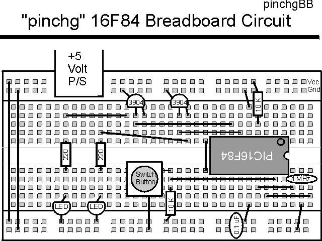
Using a breadboard, the experiment is wired using the guide:
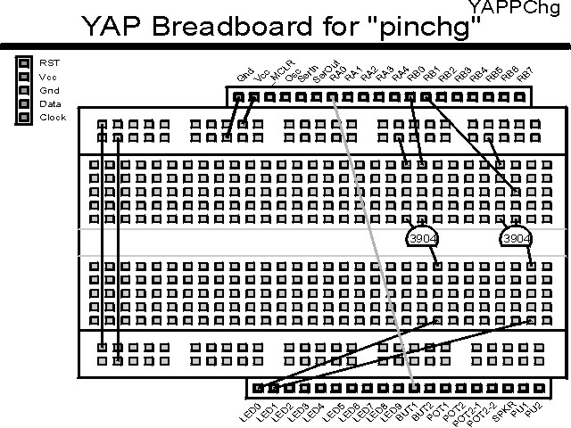
If the EMU-II or YAP-II is used, the experiment is wired as:
The source code listed below can be accessed from the CD-ROM by clicking Here.
 title  "PinChg - Change the State of an LED Inadvertently"
#define _version "1.00"
;
;  Update History:
;
;  99.11.23 - Created
;
;  This Application turns on a LED at RB0.  An input switch
;   at RA0 is then polled and when it is pressed, a LED at
;   RB4 is then turned on using the "bsf" instruction.  The
;   LEDs will be driven from PICmicro's I/O Ports directly
;   (no current limiting resistor and to Ground), so when
;   the button is pressed, the LED at RB0 should go out.
;
;  Myke Predko
;
;  Hardware Notes:
;  16F84 Running at 4 MHz
;  RA0 - Button Pulled up to Vcc and Active when pressed
;  RB0, RB1 - LED controlled by a NPN/N-Channel FET Transistor
;   with a 220 Ohm Pull Up
;
 LIST R=DEC
 ifdef __16F84
  INCLUDE "p16f84.inc"
 else
 ifdef __16F877
  INCLUDE "p16f877.inc"
 endif

;  Variable Register Declarations

;  Macros


 ifdef __16F84
 __CONFIG _CP_OFF & _WDT_OFF & _XT_OSC & _PWRTE_ON
 else
 __CONFIG _CP_OFF & _WDT_OFF & _XT_OSC & _PWRTE_ON & _DEBUG_OFF & _LVP_OFF & _BODEN_OFF
 endif

 org     0
Mainline

  nop

  clrf   PORTB			;  Initialize PortB to Nothing On
  bsf    STATUS, RP0
  movlw  0x0FC			;  Set RB0 & RB4 as Outputs
  movwf  TRISB ^ 0x080
  bcf    STATUS, RP0

  bsf    PORTB, 0			;  Turn on RB0 LED

Loop
  btfsc  PORTA, 0			;  Wait for Button to be Pressed
   goto  Loop

  bsf    PORTB, 1			;  Turn on RB1 LED
					; #### - RB0 LED Turned Off

  goto   $			;  Loop Forever


 end
For this experiment to work as desired (both LEDs on after the button is pushed), then 330® resistors should be put in series with the PORTB I/O pins and the 2N3904 transistors' bases.
Click Here to look at the twenty second experiment - TimeEnd