- FirstAp
- RegAddr
- Status
- Arith
- MidGoto
- LowGoto
- CondJump
- VarMani
- VarArray
- StackOps
- FirstCal
- StakCall
- CallBUp
- Table0
- ArbTable
- SmallTbl
- StateMC
- LEDOn
- Current Consumption Check
- Debounce
- PinChg
- TimeEnd
- Decouple
- WDT
- PowerUp
- Reset
- TMR0
- Random
- Sleep
- DiffOsc
- EEPROM
- SHORT
- ADCLess
- ADC
- VLadder
- PWMOut
- Cylon
- TMR0Int
- LEDPWM
- IntDeb
- TrueRS
- BasicRS
- SimpRS
- 3RS
- Debug
Useful Code Snippets and Macros

"PowerUp" Experiment
When MPLAB, UMPS or GPSIM power up, they all present the contents of the file registers as 0x000 (all zeros). This is not accurate and in fact the contents of the PICmicro should be assumed to be random. This experiment is designed to show what are the initial contents of the file registers and to see how they can vary from device to device (or even by powering up and down), you might want to try out this application multiple times with different PICmicro® MCUs.
The experiment uses the circuit shown below:
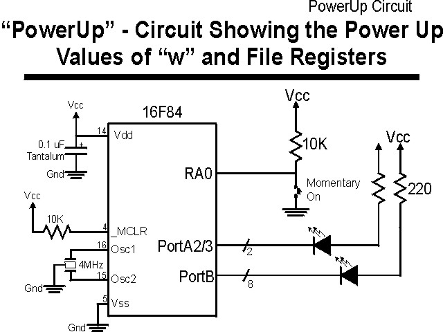
The parts needed for this experiment are listed in the table:
| Part | Description | Required for the YAP-II/EMU-II? |
|---|---|---|
| PICmicro® MCU | PIC16F84-04/P PIC16F877-04/P |
In Socket |
| Vdd/Vss Decoupling Capacitor | 0.1 uF (Any Type) | No |
| _MCLR Pull Up Resistor | 10K, 1/4 Watt | No |
| 4 MHz Ceramic Resonator | Three Leaded Ceramic Resonator with Built in 27-33pF Capacitors | No |
| RA0 Push Button | Momentary On/Modified for Breadboard | No - "BUT1" Used |
| PORTB LED Current Limiting Resistors | 10x 220W, 1/4 Watt | No - "LED1" Used |
| PORTA/PORTB LED | 10 LED "Bargraph" Recommended | No - "LED1" through "LED9" Used |
| Breadboard | Any Type | No |
| +5 Volt "Vcc" Power Supply | Any Type | No |
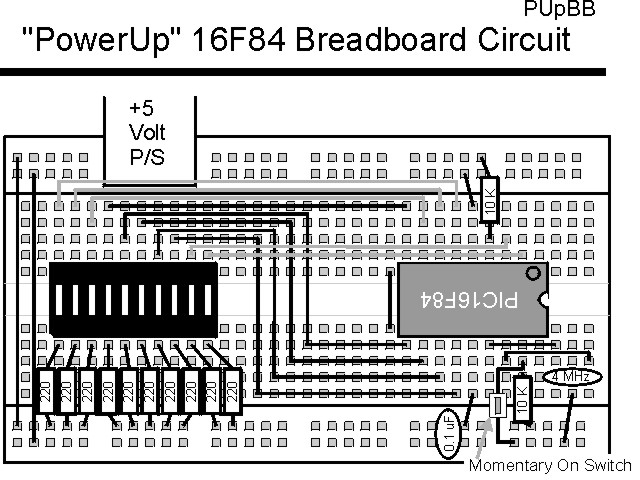
Using a breadboard, the experiment is wired using the guide:
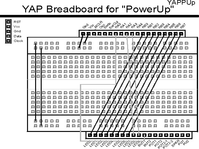
If the EMU-II or YAP-II is used, the experiment is wired as:
The source code listed below can be accessed from the CD-ROM by clicking Here.
 title  "PowerUp - List Power Up Values of "w" and 16 Registers"
#define nDebug
;
;  This Application displays the contents of "w" upon power up
;   (Reset) and as the button on RA0 is pressed, the contents of
;   the file registers from 0x030 to 0x040 are displayed on LEDs
;   connected to PORTB.  LEDs on PortA bits 2 & 3 display the
;   least significant two bits of the file register address (and
;   are both on for the "w" display.
;
;
;  Hardware Notes:
;   PIC16F84 Running at 4 MHz
;   _MCLR is Pulled Up
;   PORTA.0 is Pulled up and Connected to a Momentary "On" Switch
;   All 8 bits of PortB are Pulled up and Connected to LEDs
;   PORTA.2 is Pulled up and Connected to a LED for _PD
;   PORTA.3 is Pulled up and Connected to a LED for _TO
;
;  Myke Predko
;  99.12.26
;
  LIST R=DEC
 ifdef __16F84
  INCLUDE "p16f84.inc"
 else
 ifdef __16F877
  INCLUDE “p16f877.inc”
 endif

;  Register Usage
 CBLOCK 0x020           ;  Start Registers at End of the SFRs
Dlay:2
Temp
 ENDC

Up   EQU 1			;  Flag Value for Debounce "Up"
Down EQU -1			;  Flag Value for Debounce "Down"

;  Macros
Debounce MACRO Direction

 if (Direction < 0)	;  Going Down
  btfsc  PORTA, 0
 else
  btfss  PORTA, 0		;  Wait for Button Released
 endif
   goto  $ - 1

 ifndef Debug
  movlw  0x0100 - 0x0C4	;  Initialize Dlay for a 20 msec
  movwf  Dlay		;   Delay
  movlw  0x0100 - 0x00A
  movwf  Dlay + 1

  bcf    STATUS, Z	;  Make Sure that Zero is Reset

  incfsz Dlay, f
   goto  $ + 2
  incf   Dlay + 1, f
 if (Direction < 0)
  btfsc  PORTA, 0
 else
  btfss  PORTA, 0		;  Button Still Released?
 endif
   goto  $ - 11		;  No - Loop Around Again
  btfss  STATUS, Z	;  Zero Flag Set (20 mSecs Past?)
   goto  $ - 6
 else
  nop				;  movlw  0x0100 - 0x0C4
  nop				;  movwf  Dlay
  nop				;  movlw  0x0100 - 0x00A
  nop				;  movwf  Dlay + 1

  nop				;  bcf    STATUS, Z

  nop				;  incfsz Dlay, f
  nop				;   goto  $ + 2
  nop				;  incf   Dlay + 1, f
  nop				;  btfsc  PORTA, 0
  nop				;   goto  $ - 11
  nop				;  btfss  STATUS, Z
  nop				;   goto  $ - 6
 endif

 endm				;  End the Macro


 PAGE
 ifdef __16F84
 __CONFIG _CP_OFF & _WDT_OFF & _XT_OSC & _PWRTE_ON
 else
 __CONFIG _CP_OFF & _WDT_OFF & _XT_OSC & _PWRTE_ON & _DEBUG_OFF & _LVP_OFF & _BODEN_OFF
 endif

;  Mainline of PowerUp
  org    0

  movwf  PORTB		;  Save the Contents of "w" into PortB
  clrf   PORTA		;  Turn on Both PortA LEDs to Indicate "w"

  bsf    STATUS, RP0
  clrf   TRISB ^ 0x080	;  Make All 8 PortB Bits Output
  movlw  0x013		;  Make RA2 and RA3 Outputs/RA0 Input
  movwf  TRISA ^ 0x080
  bcf    STATUS, RP0

  movlw  0x030		;  Start Displaying the Data at Address 0x020
  movwf  FSR

Loop				;  Loop Here

 Debounce Up		;  Wait for Key to Go Up

  nop				;  Location for Stopping after
				;   "Up" Debounce
 Debounce Down		;  Wait for Key to Go Down

  rlf    FSR, w		;  Get the Current Address
  movwf  Temp
  rlf    Temp, w		;  Shift it up by 2 to Display LSBs in RA2/RA3
  xorlw  0x0FF		;  Invert the Value
  movwf  PORTA

  comf   INDF, w		;  Get the Value at FSR
  movwf  PORTB		;  Output it

  incf   FSR, f		;  Point to the Next Value
  movf   FSR, w		;  Displayed 16 File Registers?
  xorlw  0x040
  btfss  STATUS, Z
   goto  Loop

  goto   $			;  When Finished, Infinite Loop

 end