- FirstAp
- RegAddr
- Status
- Arith
- MidGoto
- LowGoto
- CondJump
- VarMani
- VarArray
- StackOps
- FirstCal
- StakCall
- CallBUp
- Table0
- ArbTable
- SmallTbl
- StateMC
- LEDOn
- Current Consumption Check
- Debounce
- PinChg
- TimeEnd
- Decouple
- WDT
- PowerUp
- Reset
- TMR0
- Random
- Sleep
- DiffOsc
- EEPROM
- SHORT
- ADCLess
- ADC
- VLadder
- PWMOut
- Cylon
- TMR0Int
- LEDPWM
- IntDeb
- TrueRS
- BasicRS
- SimpRS
- 3RS
- Debug
Useful Code Snippets and Macros

"TMR0" Experiment
TMR0 can be used in a number of different situations to keep track of the actual time instead of counting instruction cycles in an application. In TimeEnd, I showed how the timer could be kept from incrementing. In this experiment, the current value of the timer is continuously displayed on a set of eight LEDs.
The experiment uses the circuit shown below:
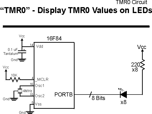
The parts needed for this experiment are listed in the table:
| Part | Description | Required for the YAP-II/EMU-II? |
|---|---|---|
| PICmicro® MCU | PIC16F84-04/P PIC16F877-04/P |
In Socket |
| Vdd/Vss Decoupling Capacitor | 0.1 uF (Any Type) | No |
| _MCLR Pull Up Resistor | 10K, 1/4 Watt | No |
| 4 MHz Ceramic Resonator | Three Leaded Ceramic Resonator with Built in 27-33pF Capacitors | No |
| PORTB LED Current Limiting Resistors | 8x 220W, 1/4 Watt | No - "LED1" Used |
| PORTA/PORTB LED | 10 LED "Bargraph" Recommended | No - "LED1" through "LED9" Used |
| Breadboard | Any Type | No |
| +5 Volt "Vcc" Power Supply | Any Type | No |
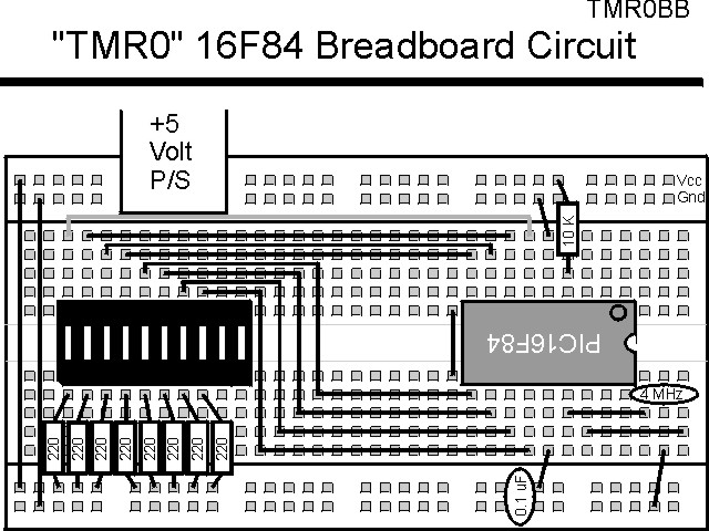
Using a breadboard, the experiment is wired using the guide:
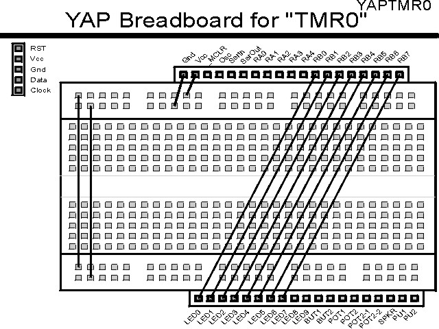
If the EMU-II or YAP-II is used, the experiment is wired as:
The source code listed below can be accessed from the CD-ROM by clicking Here.
 title  "TMR0 - Demonstrate the Operation of TMR0 with Prescaler"
;
;  This Code sets up TMR0 to run from the Instruction Clock and
;   uses the Prescaler to divide the incoming clock.
;
;
;  Hardware Notes:
;   PIC16F84 Running at 4 MHz
;   _MCLR is Pulled Up
;   All 8 bits of PortB are Pulled up and Connected to LEDs
;
;  Myke Predko
;  99.12.26
;
  LIST R=DEC
 ifdef __16F84
  INCLUDE "p16f84.inc"
 else
 ifdef __16F877
  INCLUDE "p16f877.inc"
 endif

;  Register Usage
 CBLOCK 0x020                   ;  Start Registers at End of the Values
 ENDC


 PAGE
 ifdef __16F84
 __CONFIG _CP_OFF & _WDT_OFF & _XT_OSC & _PWRTE_ON
 else
 __CONFIG _CP_OFF & _WDT_OFF & _XT_OSC & _PWRTE_ON & _DEBUG_OFF & _LVP_OFF & _BODEN_OFF
 endif

;  Mainline of TMR0
  org    0

  nop

  bsf    STATUS, RP0
  clrf   TRISB ^ 0x080		  ;  Make All 8 PortB Bits Output
  movlw  0x0FF ^ ((1 << T0CS) | (1 << PSA) | 7)
  addlw  0				  ;  Put in Prescaler Value
  movwf  OPTION_REG ^ 0x080	  ;  Load the Option Register Value
  bcf    STATUS, RP0

Loop					  ;  Loop Here

  comf   TMR0, w			  ;  Output the TMR0 Value
  movwf  PORTB

  goto   Loop


  end
In the application code, note that the
addlw 0
instruction can be given a different value, from 0 to 7, to demonstrate the effect the
prescaler has on TMR0. When the prescaler value is small ("0"), you will not see
any LEDs changing - this happens when the prescaler is larger; the most significant bits
of TMR0 will change at a visible rate.