- FirstAp
- RegAddr
- Status
- Arith
- MidGoto
- LowGoto
- CondJump
- VarMani
- VarArray
- StackOps
- FirstCal
- StakCall
- CallBUp
- Table0
- ArbTable
- SmallTbl
- StateMC
- LEDOn
- Current Consumption Check
- Debounce
- PinChg
- TimeEnd
- Decouple
- WDT
- PowerUp
- Reset
- TMR0
- Random
- Sleep
- DiffOsc
- EEPROM
- SHORT
- ADCLess
- ADC
- VLadder
- PWMOut
- Cylon
- TMR0Int
- LEDPWM
- IntDeb
- TrueRS
- BasicRS
- SimpRS
- 3RS
- Debug
Useful Code Snippets and Macros

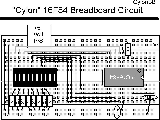
"Cylon" Experiment
Sometimes it's nice to have an indicator of whether or not an application is working properly. This experiment provides a moving "Cylon" (Named after the robots in "Battlestar Gallactica" that clanked around and said "By your command") eye that runs from a TMR0 initiated interrupt handler.
This experiment uses the circuit shown below:

The parts needed for this experiment are listed in the table:
| Part | Description | Required for the YAP-II/EMU-II? |
|---|---|---|
| PICmicro® MCU | PIC16F84-04/P PIC16F877-04/P |
In Socket |
| Vdd/Vss Decoupling Capacitor | 0.1 uF (Any Type) | No |
| _MCLR Pull Up Resistor | 10K, 1/4 Watt | No |
| 4 MHz Ceramic Resonator | Three Leaded Ceramic Resonator with Built in 27-33pF Capacitors | No |
| PORTB LED Current Limiting Resistors | 8x 220W, 1/4 Watt | No - "LED1" Used |
| PORTB LED | 10 LED "Bargraph" Recommended | No - "LED1" through "LED9" Used |
| Breadboard | Any Type | No |
| +5 Volt "Vcc" Power Supply | Any Type | No |
Using a breadboard, the experiment is wired using the guide:
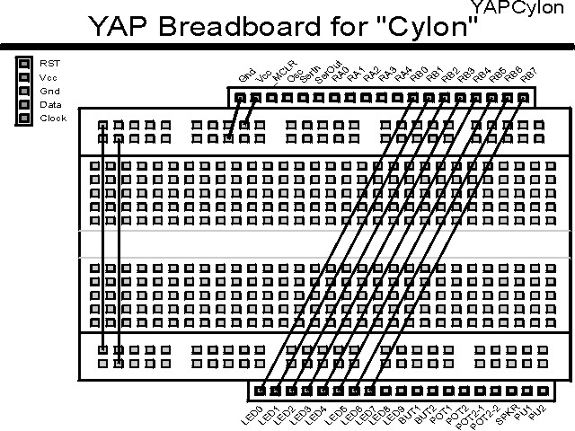
If the EMU-II or YAP-II is used, the experiment is wired as:
The source code listed below can be accessed from the CD-ROM by clicking Here.
 title  "Cylon - Output a Cylon Eye in the Background"
#define nDebug
;
;  This Application uses TMR0 to Move a "Cylon Eye" back and forth
;   Across eight LEDs connected to PORTB.
;
;  Hardware Notes:
;   This application runs on a 16F84 executing at 4 MHz
;   _MCLR is tied through a 10K Resistor to Vcc and PWRT is Enabled
;   A 220 Ohm Resistor and LED is connected between PORTB.0 and Vcc
;
;  Myke Predko
;  99.12.28
;
  LIST R=DEC
 ifdef __16F84
  INCLUDE "p16f84.inc"
 else
 ifdef __16F877
  INCLUDE "p16f877.inc"
 endif

;  Registers
 CBLOCK 0x020
_w, _status			;  Context Register Save Values
Direction			;  0 for Up, !0 for Down
Count				;  Count the Number of Times Through
 ENDC


 ifdef __16F84
 __CONFIG _CP_OFF & _WDT_OFF & _XT_OSC & _PWRTE_ON
 else
 __CONFIG _CP_OFF & _WDT_OFF & _XT_OSC & _PWRTE_ON & _DEBUG_OFF & _LVP_OFF & _BODEN_OFF
 endif

  PAGE
;  Mainline of cylon

 org     0

  nop

  movlw  2			;  Setup the Count
  movwf  Count

  goto   Mainline

 org     4
Int				;  Interrupt Handler

  movwf  _w			;  Save Context Registers
  movf   STATUS, w	;   - Assume TMR0 is the only enabled Interrupt
  movwf  _status

  bcf    INTCON, T0IF	;  Reset the Interrupt Flag

  decfsz Count, f		;  Execute Once Every Two times
   goto  IntEnd

  movlw  2			;  Reset the Counter
  movwf  Count

  btfss  PORTB, 7		;  At the Top?
   bsf   Direction, 0

  btfss  PORTB, 0		;  At the Bottom?
   bcf   Direction, 0

  btfsc  Direction, 0	;  Going Up?
   goto  Down		;  No, Down

Up				;  Moving the LEDs Up

  bsf    STATUS, C	;  Set the Status Flag
  rlf    PORTB, f		;   Shift the Data Up

  goto   IntEnd

Down

  bsf    STATUS, C	;  Shift the Data Down
  rrf    PORTB, f

IntEnd

  movf   _status, w	;  Restore the Context Registers
  movwf  STATUS
  swapf  _w, f
  swapf  _w, w

  retfie

Mainline			;  Setup PWM And Monitor it, Updating "PWMOn"

  clrf   Direction

  movlw  0x0E7		;  Start in the Middle
  movwf  PORTB

  bsf    STATUS, RP0	;  Goto Bank 1 to set Port Direction
  clrf   TRISB ^ 0x080  ;  PORTB is Output
 ifdef Debug
  movlw  0x0D0		;  Debug - Minimum Timer Delay
 else
  movlw  0x0D7		;  Normal Operation - Maximum Timer
 endif
  movwf  OPTION_REG ^ 0x080
  bcf    STATUS, RP0	;  Go back to Bank 0

  clrf   TMR0		;  Start the Timer from Scratch

  movlw  (1 << GIE) + (1 << T0IE)
  movwf  INTCON		;  Enable Interrupts

Loop				;  Loop Here

  goto   Loop		;  Let Interrupt Handler Work in the Background


 end
Click Here to look at the thirty eighth experiment - TMR0Int