- FirstAp
- RegAddr
- Status
- Arith
- MidGoto
- LowGoto
- CondJump
- VarMani
- VarArray
- StackOps
- FirstCal
- StakCall
- CallBUp
- Table0
- ArbTable
- SmallTbl
- StateMC
- LEDOn
- Current Consumption Check
- Debounce
- PinChg
- TimeEnd
- Decouple
- WDT
- PowerUp
- Reset
- TMR0
- Random
- Sleep
- DiffOsc
- EEPROM
- SHORT
- ADCLess
- ADC
- VLadder
- PWMOut
- Cylon
- TMR0Int
- LEDPWM
- IntDeb
- TrueRS
- BasicRS
- SimpRS
- 3RS
- Debug
Useful Code Snippets and Macros

"LEDPWM" Experiment
An LED can be used to demonstrate how a PWM operates. In this experiment, I vary the period of a PWM going into an LED to demonstrate how the brightness level can be changed. To create the PWM signal, I used the interrupt handler as shown in the pseudo-code:
Interrupt PWMOutput() // When Timer Overflows, Toggle "On" and "Off"
{ // and Reset Timer to the correct delay for the Value
if (PWM == ON) { // If PWM is ON, Turn it off and Set Timer
PWM = off; // Value
TMR0 = PWMPeriod � PWMOn;
} else { // If PWM is off, Turn it ON and Set Timer
PWM = ON; // Value
TMR0 = PWMOn;
} // end if
INTCON.T0IF = 0; // Reset Interrupts
} // End PWMOutput TMR0 Interrupt Handler
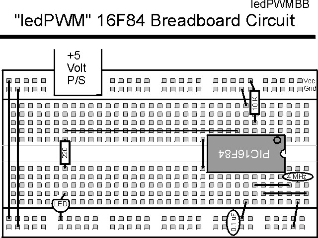
This experiment uses the circuit shown below:

The parts needed for this experiment are listed in the table:
| Part | Description | Required for the YAP-II/EMU-II? |
|---|---|---|
| PICmicro® MCU | PIC16F84-04/P PIC16F877-04/P |
In Socket |
| Vdd/Vss Decoupling Capacitor | 0.1 uF (Any Type) | No |
| _MCLR Pull Up Resistor | 10K, 1/4 Watt | No |
| 4 MHz Ceramic Resonator | Three Leaded Ceramic Resonator with Built in 27-33pF Capacitors | No |
| RB0 LED Current Limiting Resistor | 220W, 1/4 Watt | No - "LED1" Used |
| RB0 LED | Any Type | No - "LED1" Used |
| Breadboard | Any Type | No |
| +5 Volt "Vcc" Power Supply | Any Type | No |
Using a breadboard, the experiment is wired using the guide:
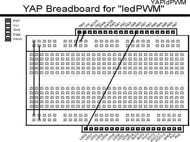
If the EMU-II or YAP-II is used, the experiment is wired as:
The source code listed below can be accessed from the CD-ROM by clicking Here.
 title  "LedPWM - Show an LED Changing Brightness"
;
;  This Application simply waits for the TMR0 interrupt handler to
;   occur and after the LED PWM "ON" is complete, decrement the "ON"
;   value.  This Application repeats endlessly with the LED getting
;   lighter before turning off and starting over.
;
;  Hardware Notes:
;   This application runs on a 16F84 executing at 4 MHz
;   _MCLR is tied through a 4.7K Resistor to Vcc and PWRT is Enabled
;   A 220 Ohm Resistor and LED is attached to PORTB.0 and Vcc
;   A 10K pull up is connected to RA0 and it's state is passed to
;    RB0
;
;  Myke Predko
;  99.12.14
;
  LIST R=DEC
 ifdef __16F84
  INCLUDE "p16f84.inc"
 else
 ifdef __16F877
  INCLUDE "p16f877.inc"
 endif

;  Registers
 CBLOCK 0x020
_w, _status                   ;  Context Register Save Values
PWMOn:2                       ;  PWM "On Value"
PWMDouble: 2                  ;  Divide PWM down for Slowing Down
 ENDC

#define PWM PORTB, 0          ;  LED on PORTB.0


 ifdef __16F84
 __CONFIG _CP_OFF & _WDT_OFF & _XT_OSC & _PWRTE_ON
 else
 __CONFIG _CP_OFF & _WDT_OFF & _XT_OSC & _PWRTE_ON & _DEBUG_OFF & _LVP_OFF & _BODEN_OFF
 endif

  PAGE
;  Mainline of ledpwm

 org     0

  nop

  clrf   PWMDouble
  clrf   PWMDouble + 1

  goto   Mainline

 org     4
Int                           ;  Interrupt Handler

  movwf  _w                   ;  Save Context Registers
  movf   STATUS, w            ;   - Assume TMR0 is the only enabled
  movwf  _status              ;     Interrupt

  btfsc  PWM                  ;  Is PWM O/P Currently High or Low?
   goto  PWM_ON
  nop                         ;  Low - Nop to Match Cycles with High

  bsf    PWM                  ;  Output the Start of the Pulse

  movlw  6 + 6                ;  Get the PWM On Period
  subwf  PWMOn, w             ;  Add to PWM to Get Correct Period for
                              ;   Interrupt Handler Delay and Missed
                              ;   cycles in maximum 1024 usec Cycles
  goto   PWM_Done

PWM_ON                        ;  PWM is On - Turn it Off

  bcf    PWM                  ;  Output the "Low" of the PWM Cycle

  movf   PWMOn, w             ;  Calculate the "Off" Period
  sublw  6 + 6                ;  Subtract from the Period for the
                              ;   Interrupt Handler Delay and Missed
                              ;   cycles in maximum 1024 usec Cycles

  goto   PWM_Done

PWM_Done                      ;  Have Finished Changing the PWM Value

  sublw  0                    ;  Get the Value to Load into the Timer
  movwf  TMR0

  bcf    INTCON, T0IF         ;  Reset the Interrupt Handler

  movf   _status, w           ;  Restore the Context Registers
  movwf  STATUS
  swapf  _w, f
  swapf  _w, w

  retfie

Mainline                      ;  Setup the PWM And then Monitor it,
                              ;   Updating "PWMOn"
  bsf    PORTB, 0             ;  Make the LED on PORTB.0 "off"
                              ;   Initially
  bsf    STATUS, RP0          ;  Goto Bank 1 to set Port Direction
  bcf    TRISB ^ 0x080, 0     ;  Set RB0 to Output
  movlw  0x0D1                ;  Setup TMR0 with a 4x prescaler
  movwf  OPTION_REG ^ 0x080
  bcf    STATUS, RP0          ;  Go back to Bank 0

  clrf   TMR0                 ;  Start the Timer from Scratch

  movlw  (1 << GIE) + (1 << T0IE)
  movwf  INTCON               ;  Enable Interrupts

Loop                          ;  Loop Here

  btfsc  PWM                  ;  Wait for PWM to go Low
   goto  $ - 1

  incfsz TMR0, w              ;  Wait for TMR0 to Equal 0x0FF
   goto  $ - 1

  movf   PWMDouble, f         ;  Decrement PWM Double
  btfsc  STATUS, Z
   decf  PWMDouble + 1, f
  decf   PWMDouble, f

  rrf    PWMDouble + 1, w     ;  Divide by 4
  movwf  PWMOn + 1
  rrf    PWMDouble, w
  movwf  PWMOn

  rrf    PWMOn + 1, w
  rrf    PWMOn, w

  addlw  255 - 0x0FE          ;  Get the High limit
  addlw  0x0FE - 0x00E + 1    ;  Add Lower Limit to Set Carry
  btfss  STATUS, C            ;  If Carry Set, then Lower Case
   movlw 0x0FC                ;   Carry NOT Set, Reset the Character
  addlw  0x00E                ;  Add Lower Limit to restore the
                              ;   Character
  movwf  PWMOn                ;  Save the New Value

  btfss  PWM                  ;  Wait for the PWM to Go High
   goto  $ - 1

  goto   Loop


 end