- FirstAp
- RegAddr
- Status
- Arith
- MidGoto
- LowGoto
- CondJump
- VarMani
- VarArray
- StackOps
- FirstCal
- StakCall
- CallBUp
- Table0
- ArbTable
- SmallTbl
- StateMC
- LEDOn
- Current Consumption Check
- Debounce
- PinChg
- TimeEnd
- Decouple
- WDT
- PowerUp
- Reset
- TMR0
- Random
- Sleep
- DiffOsc
- EEPROM
- SHORT
- ADCLess
- ADC
- VLadder
- PWMOut
- Cylon
- TMR0Int
- LEDPWM
- IntDeb
- TrueRS
- BasicRS
- SimpRS
- 3RS
- Debug
Useful Code Snippets and Macros

"SimpRS" Experiment
This experiment shows how an RS-232 interface can be implemented in a PICmicro® MCU without a packaged RS-232 interface chip or using interrupts. This experiment can be used with low-end PICmicro microcontrollers. This experiment can be implemented in a YAP-II, but I recommend that it be done on a breadboard to look at the actual 3906 transistor based RS-232 interface signals as well as prepare for the next experiment (3RS).
The receive code can be modelled using the pseudo-code:
char RSReceive() // Receive a character
{
int i;
int StartFlag = 0; // Set when Data Received
char Byte;
while (StartFlag == 0) { // Wait for Valid Read
while (StartFlag == 0) {
while (RX == Mark); // Wait for a "Start Bit"
HalfBitDlay(); // Wait half a bit
if (RX == Space)
StartFlag = 1; // Still Space, not a glitch
}
for (i = 0; i < 9; i++) { // Read in the Bits
Byte = (Byte >> 1) + RX; // Add in the Bit
BitDlay(); // Delay to the Next Bit
}
if (RX != Mark) // Is there a Stop Bit?
StartFlag = 0; // No � Ignore Byte
}
return Byte;
} // end RSReceive
The transmit code is a simple timed shift out:
RSTransmit(char Data)			//  Transmit a Byte of Data
{

int  i;
int  Byte;

  Byte = 0x0FE00 + (Data << 1);	//  Set up Data to Shift Out

  for (I = 0; I < 10; I++) {		//  Shift out the Data
    TX = Byte & 1;			//  Shift out the LSB
    Byte = Byte >> 1;			//  Shift down the Data for the
    BitDlay();				//   Next Bit
  }

}  //  end RSTransmit
This experiment uses the circuit shown below:
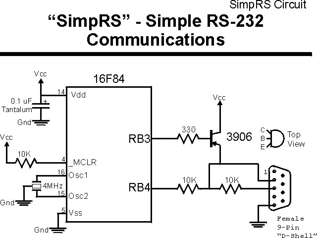
The parts needed for this experiment are listed in the table:
| Part | Description |
|---|---|
| PICmicro® MCU | PIC16F84-04/P PIC16F877-04/P |
| Vdd/Vss Decoupling Capacitor | 0.1 uF (Any Type) |
| _MCLR Pull Up Resistor | 10K, 1/4 Watt |
| 4 MHz Ceramic Resonator | Three Leaded Ceramic Resonator with Built in 27-33pF Capacitors |
| 10K, 1/4 Watt Resistors | 2x |
| Transistor Base Current Limiting Resistor | 330W, 1/4 Watt |
| 2N3906 bipolar PNP Transistor | TO-92 Package |
| 9-Pin Female "D-Shell" Connector | Modified and wired to the PC as discussed in the Book |
| Breadboard | Any Type |
| +5 Volt "Vcc" Power Supply | Any Type |
Using a breadboard, the experiment is wired using the guide:

The source code listed below can be accessed from the CD-ROM by clicking Here.
 title  "SimpRS - Simple PICmicro RS-232 Interface"
;
;  This Application executes a "Bit-Banging" RS-232 Interface
;   using a Simple Resistor/Transistor Interface.  This
;   Application Returns a "Capitalized" ASCII Input
;
;
;  Hardware Notes:
;   PIC16F84 Running at 4 MHz
;   _MCLR is Pulled Up
;   PORTB.3 is the Transmit Output
;   PORTB.4 is the RS-232 Input
;
;  Myke Predko
;  99.12.30
;
  LIST R=DEC
 ifdef __16F84
  INCLUDE "p16f84.inc"
 else
 ifdef __16F877
  INCLUDE "p16f877.inc"
 endif

;  Register Usage
 CBLOCK 0x020           ;  Start Registers at End of the Values
Byte, Count			;  Variables for RS-232
Dlay				;  Dlay Count
 ENDC

#define  TX PORTB, 3
#define  RX PORTB, 4


 PAGE
 ifdef __16F84
 __CONFIG _CP_OFF & _WDT_OFF & _XT_OSC & _PWRTE_ON
 else
 __CONFIG _CP_OFF & _WDT_OFF & _XT_OSC & _PWRTE_ON & _DEBUG_OFF & _LVP_OFF & _BODEN_OFF
 endif

;  Mainline of SimpRS
  org    0

  nop

  bsf    TX			;  Start Sending a "1"
  bsf    STATUS, RP0
  bcf    TX			;  Enable TX for Output
  bcf    STATUS, RP0

Loop

  btfss  RX			;  Wait for a Start Bit
   goto  $ - 1

  call   HalfBitDlay	;  Wait 1/2 a Bit

  btfss  RX			;  Make Sure Bit is Still Low
   goto  Loop

  movlw  8
  movwf  Count

RXLoop			;  Loop Here to Read in the Byte

  call   BitDlay		;  Wait a Full Byte

  bcf    STATUS, C	;  Set Carry Accordingly
  btfss  RX			;  Bit High or Low?
   bsf   STATUS, C

  rrf    Byte, f		;  Shift in the Byte

  goto   $ + 1		;  Make 11 Cycles in Loop
  goto   $ + 1

  decfsz Count, f
   goto  RXLoop

  call   BitDlay		;  Make Sure there is a "Stop" Bit

  btfsc  RX
   goto  Loop		;  Not High, Then No Byte

  movf   Byte, w		;  Change Byte to Upper Case
  addlw  255 - 'z'      ;  Get the High limit
  addlw  'z' - 'a' + 1  ;  Add Lower Limit to Set Carry
  btfss  STATUS, C      ;  If Carry Set, then Lower Case
  addlw  h'20'          ;   Carry NOT Set, Restore Character
  addlw  'A'            ;  Add 'A' to restore the Character
  movwf  Byte

  movlw  10			;  Send Upper Case Back with Start and Stop
  movwf  Count
  bcf    STATUS, C

TXLoop

  btfsc  STATUS, C	;  Send the Bit in "Carry"
   goto  $ + 4
  nop				;  Send a "Low"
  bcf    TX
  goto   $ + 3
  bsf    TX			;  Send a "High"
  goto   $ + 1		;  6 Cycles in Loop

  call   BitDlay		;  Wait a Bit

  bsf    STATUS, C	;  Shift Out the Next Bit into Carry
  rrf    Byte, f

  decfsz Count, f		;  11 Intrinsic Delays in TXLoop
   goto  TXLoop

  goto   Loop


BitDlay			;  Delay 833 - 15 Cycles (including
;   Call/Return)
  movlw  204
  addlw  0x0FF		;  Take 1 Away from the Loop
  btfss  STATUS, Z
   goto  $ - 2

  goto   $ + 1

  return

HalfBitDlay			;  Delay (833 - 15) / 2 Cycles

  movlw  100
  addlw  0x0FF		;  Take 1 Away from the Loop
  btfss  STATUS, Z
   goto  $ - 2

  return


 end