- FirstAp
- RegAddr
- Status
- Arith
- MidGoto
- LowGoto
- CondJump
- VarMani
- VarArray
- StackOps
- FirstCal
- StakCall
- CallBUp
- Table0
- ArbTable
- SmallTbl
- StateMC
- LEDOn
- Current Consumption Check
- Debounce
- PinChg
- TimeEnd
- Decouple
- WDT
- PowerUp
- Reset
- TMR0
- Random
- Sleep
- DiffOsc
- EEPROM
- SHORT
- ADCLess
- ADC
- VLadder
- PWMOut
- Cylon
- TMR0Int
- LEDPWM
- IntDeb
- TrueRS
- BasicRS
- SimpRS
- 3RS
- Debug
Useful Code Snippets and Macros

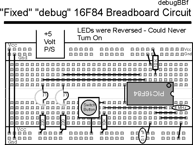
"Debug" Experiment Answers
How did you do? You should have found:
- Two wiring errors
- Three source code errors
- One questionable statement
In the book text, I review how these problems should have been found.
The correct breadboard circuit is:
The corrected source code listed below can be accessed from the CD-ROM by clicking Here.
 title  "debugfix - An application with a few problems -- FIXED"
;
;  This is an application to demonstrate how insidious some problems
;   can be.  This application has the three source code problems
;   fixed.  The error lines are commented out with the correct line
;   underneath them.
;
;  The application will initially turn on a LED at RB1 and wait for
;   a button to be pressed.  When it is, an LED at RB0 should be turned
;   on as well.
;
;  Hardware Notes:
;   PIC16F84 running at 4 MHz
;   _MCLR is tied through a 4.7K Resistor to Vcc and PWRT is Enabled
;   A 220 Ohm Resistor and LED is attached to PORTB.0/PORTB.1 and Vcc
;   A 10K pull up is connected to RA0 with a Momentary on Switch
;
;  Myke Predko
;  99.12.07
;
  LIST R=DEC
 ifdef __16F84
  INCLUDE "p16f84.inc"
 else
 ifdef __16F877
  INCLUDE "p16f877.inc"
 endif

;  Registers

; __CONFIG _CP_OFF & _WDT_ON & _XT_OSC & _PWRTE_ON
 __CONFIG _CP_OFF & _WDT_OFF & _XT_OSC & _PWRTE_ON

  PAGE
;  Mainline of debugfix

 org     0

  nop

  movlw  0x001			;  LED at RB1 is On/RB0 is Off
  movwf  PORTB

  bsf    STATUS, RP0          ;  Goto Bank 1 to set Port Direction
  movlw  0x0FC			;  Set RB0/RB1 to Output
;  movwf  TRISB ^ 0x090
  movwf  TRISB ^ 0x080
  bcf    STATUS, RP0          ;  Go back to Bank 0


Loop
  btfsc  PORTA, 0			;  Wait for RA0 Button to be Pressed
   goto  Loop

;  clrf   PORTA			;  Set RB0 = RB1 = 0 for Both LEDs on
  clrf   PORTB			;  Set RB0 = RB1 = 0 for Both LEDs on

;  goto   Loop			;  Loop Forever
  goto   $				;  Loop Forever


 end
You are now ready to start on your own applications!