- TrainCtl
- SLI
- Ultra
- Key
- Clock
- XMAS
- FanCtrl
- IRTank
- IRBetter
- Thermo
- MaryaToy
- MaryaBas
- PCTherm
- Servo
- MIC-II
- Video
- PIC17Dev
- Fuzzy
- RTOS1
- RTOS2

"PCTherm" Project
This project actually consists of three projects. The first is the remote PICmicro® MCU with a DS1820 digital thermometer chip. This interfaces to a PC ISA card via an RS-485 interface. Last, the User interfaces to this application using a Visual Basic interface. When I built the prototype, I first worked on the PICmicro MCU USART interface to the remote temperature sensor and then developed the Visual Basic interface for the user.
Click Here to look at the PICmicro MCU code executing on the ISA card.
The ISA card circuit used for this application is in pdf format and can be seen Here.
The bill of materials for ISA card circuit is listed in the table below.
| Part | Description |
|---|---|
| U1 | PIC16F877-04/P |
| U2 | 75176 RS-422/RS-485 Interface |
| U3 | 74LS138 3 to 8 Demultiplexor |
| U4 - U5 | 74LS85 Value Comparators |
| CR1 | Red LED (Any Type) |
| Y1 | 4 MHz Ceramic Resonator with Internal Capacitors |
| R1 | 4.7K, 1/4 Watt Resistor |
| R2 | 220 Ohm, 1/4 Watt Resistor |
| C1, C3 - C5 | 0.1 uF, 16 Volt Tantalum Capacitor |
| J3 | 4x1 Screw Terminal |
| Miscellaneous | ISA Prototyping Cards, Sockets, Wiring |
Click Here to look at the PICmicro MCU code executing on the remote temperature sensor card.
The Remote card circuit that I created for this application is:
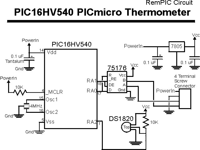
The bill of materials for ISA card circuit is listed in the table below.
| Part | Description |
|---|---|
| PIC16HV540 | PIC16HV540-JW |
| 7805 | 7805 +5 Volt Regulator |
| DS1820 | DS1820 TO-92 Package |
| 75176 | 75176 RS-422/RS-485 Interface |
| 4 MHz | 4 MHz Ceramic Resonator with Internal Capacitors |
| 10K | 2x 10K, 1/4 Watt Resistor |
| 3x 0.1 uF | 0.1 uF, Tantalum Capacitors |
| Connector | 4x1 Screw Terminal |
| Miscellaneous | Prototyping Cards, Sockets, Wiring |
To Connect the remote card to the PC ISA card, I used standard, 4 Conductor telephone cable wired as:
| Color | Function |
|---|---|
| Red | +12 Volts |
| Black | Ground |
| Yellow | "A" Pin (Positive RS-485 Voltage I/O) of 75176 |
| Green | "B" Pin (Positive RS-485 Voltage I/O) of 75176 |
Click Here to load the Visual Basic application that will display/monitor the temperature read by the remote card.