- TrainCtl
- SLI
- Ultra
- Key
- Clock
- XMAS
- FanCtrl
- IRTank
- IRBetter
- Thermo
- MaryaToy
- MaryaBas
- PCTherm
- Servo
- MIC-II
- Video
- PIC17Dev
- Fuzzy
- RTOS1
- RTOS2

"Key" Project
Wiring a switch matrix keyboard to a PICmicro® microcontroller is not that difficult a task - probably the most difficult part of the exercise is figuring out how to wire the two devices together. This is probably the one project that you will not be able to reproduce exactly, as I believe the keyboard I used was unlabeled (except for a "General Instruments" stamp on the back) and a marking of "Pin 1" on the ribbon cable that came out of the end of it. In the text for this experiment, I review how I figured out how this switch matrix keyboard was wired and how I arranged the I/O pins for wiring to the PICmicro.
Click Here to look at the application's source code.
The circuit used for this application is:
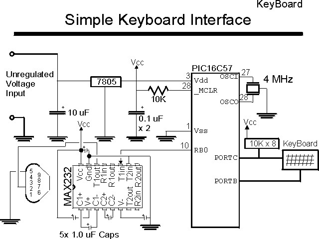
The bill of materials for this application is:
| Part | Description |
|---|---|
| PIC16C57 | PIC16C57-JW |
| 7805 | 78L05 +5 Volt Regulator |
| MAX232 | Maxim MAX232 RS-232 Interface Chip |
| 4 MHz | 4 MHz Ceramic Resonator with built in 27-33 pF Capacitors |
| 10K | 10K, 1/4 Watt Resistor |
| 10K x 8 | 10K Common Tap, 9 Pin "SIP" Resistor |
| 10uF | 10uF, 16 Volt Electrolytic Capacitor |
| 5x 1.0uF | 1.0uF, 16 Volt Capacitor (Any Type) |
| RS-232 Connector | 9 Pin, Male D-Shell Connector with Solder Tail Connections |
| Miscellaneous | Switch Matrix Keyboard, Breadboard Prototyping System, Wiring |