- MPLAB IDE
- gpasm/gpsim
- El Cheapo
- YAP-II
- EMU-II
- UMPS
Useful Code Snippets and Macros

El Cheapo Programmer
Included with this book is a PCB that you can use to build your own PICmicr® microcontroller programmer. The programmer's name is the "El Cheapo" and reflects my efforts to create the least expensive programmer possible that would work on the widest variety of PCs by interfacing to their Parallel (Printer) Ports. This is actually quite a challenge because of the staggering variety of PCs that have been on the market.
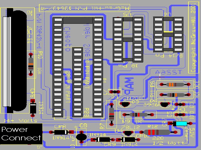
The PCB provided here is designed to work with all the different PICmicro® MCU part numbers that come in "DIP" packages and can be programmed using the five line "ICSP" protocol. This means that virtually all the mid-range PICmicro MCUs can be programmed with the El Cheapo as well as a number of the Low-End parts (the PIC12CXXX and PIC16C505). The only mid-range parts that cannot be programmed using this programmer is the PIC14000 and the 20 pin PICmicro MCUs. The El Cheapo cannot be used for the PIC17CXXX and could be used with PIC18CXX2 (but I have not written the software to support the PIC18CXX2). The range of supported PICmicro MCU part numbers includes basically all the devices that are presented in the Experiments, Projects and Tools of this book. The part selection mechanism of the El Cheapo is based on a file table and can be easily updated when new parts become available.
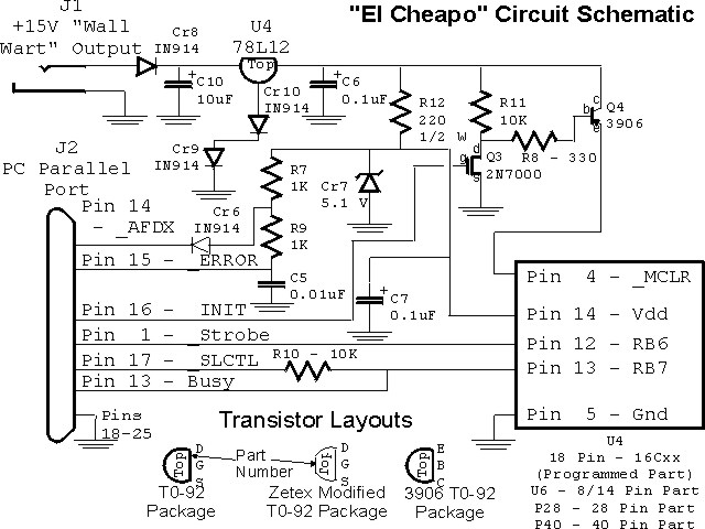
To be as "universal" as possible, the El Cheapo circuit (shown below) uses the "handshaking" lines of the PC's parallel port instead of the data lines. This was done in order to allow the El Cheapo to work on PCs that did not have ECP, EPP or even basic bi-directional parallel ports. For the most part, this effort was successful, but there are a few things that can happen which will make it difficult for you to get your own "El Cheapo" working. At the end of this page, I have included a list of the most common errors made by people building their own versions of the El Cheapo. The circuit provided here is the fourth version of the original and incorporates a number of lessons that I have learned over a year of helping people build their own - chances are you will find that your El Cheapo will work right off the bat.
| Part | Description/Comments |
|---|---|
| U4 | 78L12 +12 Volt, 100 mA Linear Voltage Regulator |
| U5 | 18 Pin 0.300" DIP Socket. 18 Pin "ZIF" Socket Recommended |
| U6 | 14 Pin 0.300" DIP Socket. 18 Pin "ZIF" Socket Recommended |
| P28 | 14 Pin 0.100" Socket Strip. This is one half of a 28 Pin DIP Socket cut down as described in the Text |
| P40 | 40 Pin 0.600" DIP Socket. This is a 40 Pin DIP Socket cut down as described in the Text |
| Q3 | 2N7000 N-Channel MOSFET Transistor |
| Q4 | 2N3906 PNP Bipolar Transistor |
| CR6, CR8 - CR10 | 1N914 Small Signal Silicon Diode. Any Small Signal Silicon Diode can be used for this application |
| CR7 | 5.1 Volt, 1/2 Watt Zener Diode |
| R7, R9 | 1 K, 1/4 Watt Resistors |
| R8 | 330W, 1/4 Watt Resistor |
| R10, R11 | 10 K, 1/4 Watt Resistors |
| R12 | 220W, 1/2 Watt Resistor. Note that this resistor is rated at 1/2 Watt |
| C5 | 0.01 uF Capacitor (Any Type) |
| C6, C7 | 0.1 uF, 16 Volt Tantalum Capacitors |
| C8 | 10 uF, 35 Volt Electrolytic Capacitor |
| J1 | 2.5 mm PCB Mount Power Socket. CUI Stack Part Number PH-202B (Digi-Key Part Number CP-202B-ND) |
| J2 | 25 Pin Female 90 Degree PCB Mount D-Shell Connector. Note - Male Connector CANNOT be used |
| N/A | Four Rubberized "Feet" for PCB. This is Optional, but Recommended to avoid the El Cheapo from scratching table |
| Parallel Cable | 6'/10' 25 Pin D-Shell Male to Male "Parallel Transfer Cable". May be labled "Interlink" |
| Power Supply | 14+ Volt, 300+ mA AC/DC ("Wall Wart") Power Supply with 2.5 mm Power Plug output |
| Miscellaneous | PICmicro® microcontrollers, Controlling PC, EPROM Eraser |
| Tools | Digital Multi-Meter, Soldering Iron, Solder, Clippers, Needle Nose Pliers, Flat Bladed Screwdriver, Magnifying Glass |
For best results, I recommend that you use the specified parts as much as possible. Many of these parts are available from "Radio Shack" or other retail electronic stores. If you have any problems finding parts, please let me know and I will see what I can do about pointing you in the right direction. The costs for the parts needed to build the El Cheapo range anywhere from $10 (USD) to $60 (USD) depending on the source of the parts as well as whether or not ZIF sockets are used with the programmer.
Once you have all the parts together, I recommend that you get your PC ready for
the El Cheapo. The PC should have the following characteristics:
Note that I indicated that there should be a "free" (unused) Parallel (Printer) Port
on the PC you are going to use the El Cheapo with. Some people have used the El Cheapo successfully
on a Parallel Port that is shared with another device (ie a printer) and have not had any problems.
I do not recommend doing this because the El Cheapo interfaces to the PC using a non-standard
protocol and if the switch is not made and the software initiated, you may find that the printer
will be put into an invalid mode or if the reverse is true, you may find the El Cheapo working
unpredictably. A Parallel Port PCI or ISA adapter is less than $20 (USD) and will simplify your
life immesurably.
For the software I have provided, I rely on the "standard" Parallel Port addresses
(0x0378, 0x03BC and 0x0278). The following instructions are for a Microsoft "Windows" PC. If you
are running MS-DOS, then you will probably be using a standard "SPP" or Bi-Directional parallel
port and there will be no ability to change the port addresses. Linux users will have to consult
their Parallel Port "Plug and Play" resource documentation.
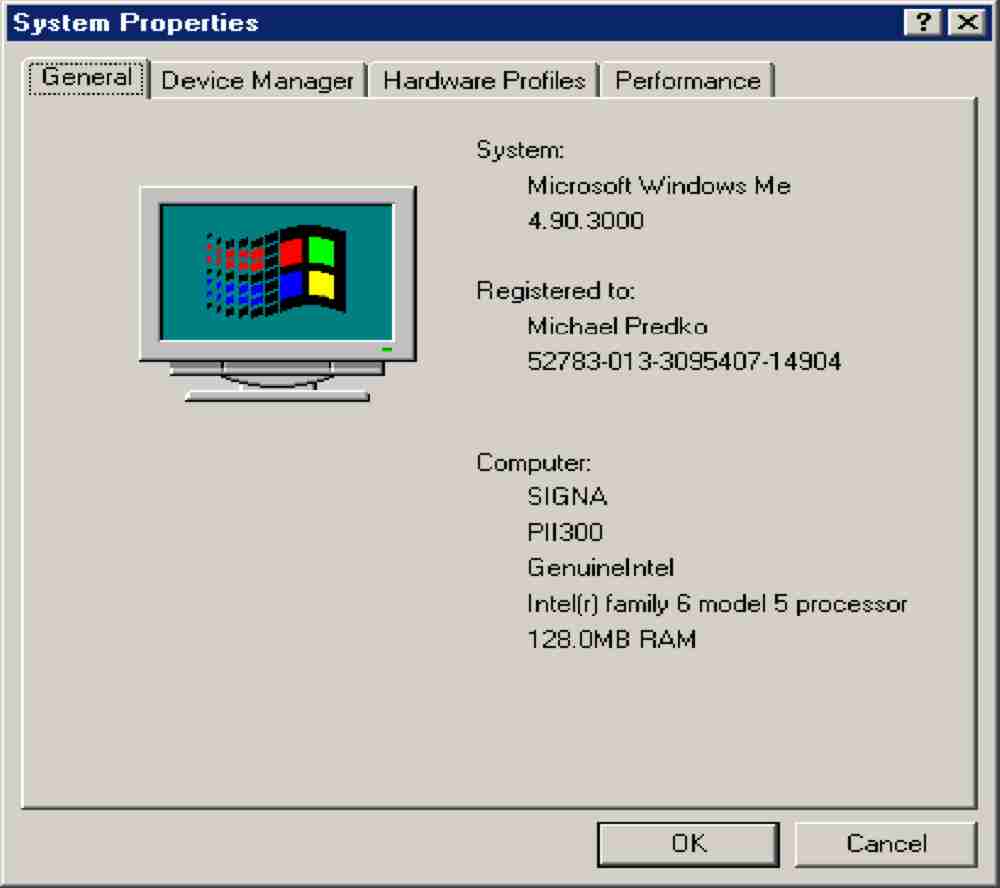
You may find that a new "Plug and Play" device sets the application
up at a non-standard address. This can be checked by clicking on "Start" -> "Settings" ->
"Control Panel" and then initiating "System".
Next, click on the "Device Manager" tab to display the hardware devices recognized
within the PC. Click on "Ports (COM and LPT)" to see the different communications avenues
available as "standard" hardware. Click on the parallel ("LPT") port that the El Cheapo is to be
connected to and then click on "Properties".
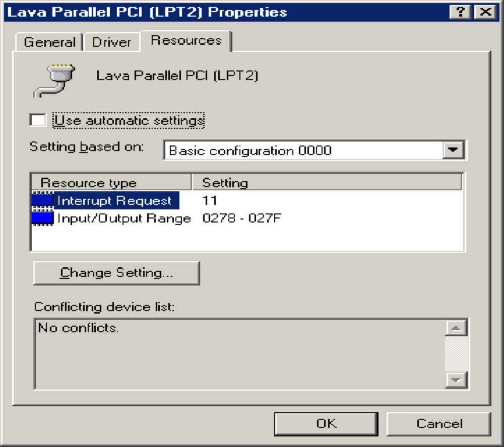
Once the Parallel Port "Properties" dialog box is displayed, click on the "Resources"
tab to see what address the port is set to. This is shown in the second screen shot to the right.
if the address range is not 0x0378-0x037F, 0x03BC-0x03BF or 0x0278-0x027F, then consult the manual
for the Parallel Port to find out how to change the address of the Parallel Port so that it is in
one of the correct ranges.
With the parallel port set up correctly in the PC, I recommend that you now load in
the MPLAB IDE from the CD-ROM and copy the book's application source files as is specified in
File Copying/Harddrive Setup.
If you are an MS-DOS user, you can use
eldebug.exe to test out your application design while
you are building it as I outline below. El Debug and
elcheapo.exe (the El Cheapo MS-DOS programming utility)
are Version 3.1 tools for the original El Cheapo application. They will program all mid-range
PICmicro MCUs that do not require oscillator calibration loading. The two applications can be
found at in the "C:\PICmicro\code\elcheapo" directory of your PC.
For this book, I recommend that you use the Microsoft "Windows" version of the
El Cheapo interface software. This software can be used for both building and debugging your
programmer as well as the primary interface for programming PICmicro devices.
Before attempting to load the El Cheapo Windows application software, you should
make sure that you have a "C:\Program Files" directory (folder) on your PC. For most Windows users,
this is not an issue, but over the past few months, I have had to help some individuals that have
non-standard installations of Windows and do not have the "C:\Program Files" directory. The
"C:\Program files" directory is used to store the PICmicro MCU part number data files, the user
preference files as well as the PCB layout graphics and if it is not present, the Windows
installation program will fail to properly install the files, but you will not be notified of the
error.
The first step in the process of installing the El Cheapo Windows interface is to
load the "Port95NT" device driver. When
Port95NT is clicked on, the PC will be loaded with a set of
DLLs that allow the Windows Interface to access the hardware registers of the PC. This package
will be required for one of the experiments and should not be removed once it is on your PC.
With the PC setup and Port95NT set up, you
can now click Here to load the El Cheapo Windows
interface. Loading should just take a few seconds and when it has finished, you can start up the
El Cheapo Windows interface by clicking on "Start" -> "Programs" followed by the "El Cheapo Windows
Interface".
The following procedures should be followed to set up and assemble the El Cheapo
programmer. In order to make sure that this operation goes as smoothly as possible, I recommend
that you get the El Cheapo Windows Interface up and running before you begin to assemble the
programmer. The five steps that should be taken before starting to build the El Cheapo programmer
are:
The instructions in the "Build/Test" option will be used to guide you with which
parts are placed on the board at each step. I have built six different "El Cheapos" and this is the
order in which I have found the operations to be most efficient. You may encounter some problems
that you can't figure out. If this happens, look down at
Common El Cheapo Programmer Problems and their Solutions as your first
line of defense.
Warnings:
I do not have a stack of El Cheapo boards waiting to be sent to people who
incorrectly build their first ones. If you want a replacement board you will either have to buy
another book or have a quick-turn PCB house build what I am calling "PCB1". A little care at the
start will keep you from ruining the board or taking a long time to get it running. When you are
getting ready to build the programmer, here are some points to keep in mind:
I hope you understand that most of these instructions are common sense, but as
somebody much smarter than me noted, nothing seems to be so uncommon as common sense.
Once you have everything together and you are ready, follow the assembly
instructions below. Note that in virtually every step I ask for a voltage measurement and
occasionally a test operation from the PC - always disconnect the power and the PC after
testing the components for the current assembly step and going on to the next one.
That's it for the El Cheapo PCB assembly. It is not a terribly hard PCB to build,
but if you are new to electronics, you should make sure you plan what you are going to do before
hand and don't do anything until you are sure that you're going about it correctly. If you are
running under MS-DOS, you will have to follow the same basic instructions, but use the "El Debug"
application.
Operation of the programmer is quite simple, regardless of whether you are running
under MS-DOS or Microsoft "Windows". For most people, I recommend that you use the Windows Interface
as this is the easier interface to work with and it will program calibration values and work with the
low-end ICSP programmed PICmicros quite intuitively. The MS-DOS interfaces are quite competent for
the mid-range devices, but I have yet to figure out a clear, intuitive set of command line parameters
for them to encompass different device types and features. If you have any ideas - please email
them to me.
Both El Cheapo interfaces execute at approximately the same speed. You may find
that the Windows version is even faster in some situations. Both interfaces program PICmicro MCUs
using the Microchip specified algorithms which are explained in the Datasheets
pages.
The MS-DOS "elcheapo.exe" application
is invoked with the following command line statement:
Where:
PC Preparation
El Cheapo Assembly
Software Operating Instructions
elcheapo ProgName[.hex] [/1|/2|/3] [/v] [/e]
| Command | Description/Comments |
|---|---|
| ProgName[.hex] | Hex File to be programmed into the PICmicro MCU |
| [/1|/2|/3] | The parallel port to use with the El Cheapo (specified as "/1", "/2" or "/3"). The MS-DOS version will "pick up" the Parallel Port addresses from BIOS, so the actual port addresses do not have to be specified. If no parallel port is specified, then LPT1 is used by default |
| [/v] | When "/v" is specified on the command line, the El Cheapo "verifies" the contents of the PICmicro MCU to the specified Hex File. If "/v" is not specified, then the PICmicro will be programmed with the contents of "ProgName[.hex]" |
| [/e] | When "/e" is specified on the command line, the El Cheapo uses the "EPROM" programming algorithm specified in Datasheets. If the "/e" parameter is not present, then the El Cheapo software carries out the programming operation using the "Flash" programming algorithm. |
As well as being much more attractive than the command line interface, the El Cheapo Windows Interface is a lot easier to use without any documentation. As can be seen in the screen shot below, the El Cheapo Windows Interface allows you to simply select the PICmicro MCU part number, the Parallel port as well as the operation to carry out:
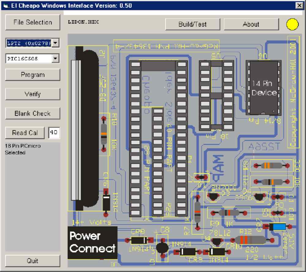
The controls on the El Cheapo Windows Interface consist of:
| Control | Operation/Comments |
|---|---|
| File Selection | Select the Hex File to be programmed into the PICmicro MCU. This is stored in the "Preferences" file to avoid having to enter the information repeatedly. |
| Parallel Port Select | The El Cheapo Windows Interface relies on actual port addresses rather than LPT numbers. This value is also stored in the "Preferences" file to avoid having to select the Parallel port to use repeatedly. |
| PICmicro® MCU Part Number Select | The part to be programmed is selected by the user. When programming operations take place, The El Cheapo Windows Interface will store the program memory size and type as well as whether or not a calibration value is required. The PICmicro MCU part number data is in a table file which can be updated without requiring a rebuild of the application. The selected PICmicro MCU part number is stored in the "Preferences" file to avoid having to be reselected. Note that when a new PICmicro MCU part number is selected, the El Cheapo Windows Interface graphic changes to show where the PICmicro MCU is to be inserted into the card for programming. |
| Program | When Clicked, the "Program" Control will initiate programming of the PICmicro MCU. If the device has Flash program memory, it will first be erased. If the device has EPROM program memory, programming will start immediately. Note that a "Blank Check" is not done before EPROM programming. The latest version of the Hex File is programmed into the device and not the version that was available when the application was first selected - this will allow the user to update the application file rather than have to reselect it after an PICmicro MCU application rebuild. If there there is a failure during programming, the operation will stop and the results displayed. Note that the Configuration Registers are programmed according to the contents of the Hex File - to ensure that they are being programmed, use the "__CONFIG" statement in your source code. If the device requires a calibration value, the entered or read in value on the El Cheapo Windows Interface Dialog Box will be programmed into the device. |
| Verify | The "Verify" Control will initiate a comparison of the contents of the PICmicro program memory to the contents of the of the PICmicro MCU. If there is a miscompare, then the verify operation stops and the data is immediately displayed. Like the "Program" control, "Verify" operation uses the latest Hex File available on the PC's Hard Drive. Note that PIC12C50X and PIC16C505 devices will fail "Verify" after programming due to changes in how the data is read back after the Configuration Register is written to. |
| Blank Check | The "Blank Check" Control will initiate a comparison of the contents of the PICmicro program memory to see if the program memory is fully erased. The configuration registers are checked, but the calibration addresses are ignored. Note that Flash devices are erased by the El Cheapo and do not need to be checked. |
| Blank Check | The "Blank Check" Control will initiate a comparison of the contents of the PICmicro program memory to see if the program memory is fully erased. The configuration registers are checked, but the calibration addresses are ignored. Note that Flash devices are erased by the El Cheapo and do not need to be checked. |
| Cal Read | Reading the pre-programmed calibration value is invoked by clicking on the "Cal Read" control. Due to the conventions used by Microchip, the calibration values are at the end of program memory and the El Cheapo Windows Interface will have to set the PICmicro MCU's program counter to the last address in order to read the calibration value. Along with the control, there is a text input box that can be used for manually entering the hex calibration value for the PICmicro MCU. When the application is programmed into a blank PICmicro MCU, the calibration address is checked to see if it is blank and if it is, then the least significant two digits of this hex value is used. If any of the digits are incorrect, the calibration value 0x0FF is programmed into the PICmicro MCU. |
| Build/Test | The "Build/Test" control will open up the "Build/Test" portion of the El Cheapo Windows Interface and close it when clicked again. When the "Build/Test" mode of the El Cheapo Windows Interface is active, the Programming polling is stopped and the Programming modes of interface are disabled. Clicking on "Debug End" will also terminate the "Build/Test" mode of the El Cheapo Windows Interface. |
| About | Clicking on the "About" control will show the El Cheapo Schematic as well as pointers to my email ID and web page. |
| The Sun | The yellow circle in the top right hand corner of the El Cheapo Windows Interface Dialog box indicates whether or not the El Cheapo programmer is connected to the PC. If the El Cheapo programmer is not connected to the PC, then what I call "The Sun" will turn black. |
Really, the only thing to watch for with using the El Cheapo Windows Interface is the lack of the a "Blank Check" before programming. I debated on this one, but it does allow people to use "Patch Space" with the programmer.
In the next section, I have listed some common problems and the solutions around them before sending me an angry email saying the El Cheapo doesn't work, please work through the different test options that I have made available to you and make sure you don't have any of the problems listed below. In my first reply back to you I will probably be asking if you have worked through the debug options as well as the common problems listed below - please list your PC, what operating system(s), parallel port type, symptoms and what you've done to try and characterize the problem. This will help me to point you in the right direction much faster than sending back a message at a time.
The El Cheapo was originally presented as a Rentron article. This turned out to be an excellent method of prototyping the application (product) and finding out how to best design it to work with a number of different applications. As I have indicated, this is the fourth version of the design and I believe that it is quite robust. The two things I would do differently if I had to do the project over would be to a) change the 28/40 pin area so a single 40 Pin ZIF socket could be used and b) design it so that an ECP/EPP interface could take advantage of the hardware (and eliminate the need for the RC delay network). I am sure that many other people would approach the problem differently and probably more efficiently.
I am interested in your suggestions about how the El Cheapo works and if you have any ideas for how it could work better for you. Please send me an email (or better yet, publish it on the PICList for other's comments).
Good luck with your El Cheapo and I hope it gives you many hours of service!
myke
Over the year before this book was published that the El Cheapo has been built by
various people, I have found a number of recurring problems. Most of them I have not seen myself,
but they are things that you should watch out for:
Common El Cheapo Programmer Problems and their Solutions