Useful Code Snippets and Macros
- Useful Snippets and Macros
- 16 Bit Arithmetic
- Internal Peripheral Interface Code and Macros
- External Device Interface Macros
- Rentron Articles

External Device Interface Macros
Here are a set of three macros that I use for interfacing with common devices using the PICmicro. Each set of macros is quite large, but you will find that they are quite general and can save you hours trying to figure out how to come up with the LCD, Serial Port and I2C Device Interfaces.
1. LCD Interface Macros
Here are some LCD Interface Macros that can be used to interface with Hitachi 44780 based LCDs. More information about these Macros and how they are used can be found in the book.
The first is an 8 bit interface with "Busy Flag" polling. This interface will be the fastest of the three presented - but will also require the most PICmicro® MCU Interface pins.
LCD8Poll Macro DataPort, EPort, EPin, RSPort, RSPin, RWPort, RWPin,Freq
variable Dlay5Value, Dlay160Value, Dlay160Bit1 = -1, Dlay160Bit2 = -1
variable BitCount = 0
variable Value = 128, Bit = 7
errorlevel 0,-224
Dlay5Value = ((5007 * (Freq / 1000) / 4000) / 7) + 256
Dlay160Value = (163 * (Freq / 1000) / 4000) / 3
while (Bit >= 0) ; Find the Number of Bits and their
; Positions in ōDlay160Valueö
if ((Dlay160Value & Value) != 0)
if (Dlay160Bit1 == -1) ; Set the Upper Bit
Dlay160Bit1 = Bit
else
if (Dlay160Bit2 == -1)
Dlay160Bit2 = Bit
endif
endif
BitCount = BitCount + 1
endif
Value = Value >> 1
Bit = Bit - 1
endw
if (BitCount > 2) ; Just Want max two Bits
if ((Dlay160Bit1 - 1) == Dlay160Bit2)
Dlay160Bit1 = Dlay160Bit1 + 1 ; Shift Top up by 1
Dlay160Bit2 = -1 ; Delete Second
else
Dlay160Bit2 = Dlay160Bit2 + 1 ; Shift Bottom up by 1
endif
endif
Dlay5 ; Delay 5 msecs
movlw (Dlay5Value & 0x0FF00) >> 8
movwf Dlay
movlw Dlay5Value & 0x0FF
subwf Dlay, w
xorlw 0x0FF
addwf Dlay, w
btfsc STATUS, Z
decfsz Dlay, f
goto $ - 5
return
LCDPORTInit ; Initialize the I/O Ports
bsf STATUS, RP0 ; ONLY used by mid-range
movlw 0x000
movwf DataPort
bcf EPort, EPin
bcf RSPort, RSPin
bcf RWPort, RWPin
bcf STATUS, RP0
bcf EPort, EPin
bcf RSPort, RSPin
bcf RWPort, RWPin
return
LCDIns ; Send the Instruction to the LCD
movwf Dlay
movlw 0x0FF ; Read the "BF" Flag
tris DataPort
bcf RSPort, RSPin ; Read the Instruction Register
bsf RWPort, RWPin
goto $ + 1
bsf EPort, EPin
nop
movf DataPort, w ; Read the Data Port Value
nop
bcf EPort, EPin
andlw 0x080 ; Is the High Bit Set?
btfss STATUS, Z
goto $ - 7
bcf RWPort, RWPin
movlw 0 ; Put the DataPort Back into Output Mode
tris DataPort
movf Dlay, w ; Get the Saved Character
movwf DataPort
if (Freq > 8000000) ; Make Sure Proper Delay is In Place
if (Freq < 16000000)
nop
else
goto $ + 1
endif
endif
bsf EPort, EPin
if (Freq > 8000000) ; Make Sure Proper Delay is In Place
if (Freq < 16000000)
nop
else
goto $ + 1
endif
endif
bcf EPort, EPin
return
LCDChar ; Send the Character to the LCD
movwf Dlay
movlw 0x0FF ; Read the "BF" Flag
tris DataPort
bcf RSPort, RSPin ; Read the Instruction Register
bsf RWPort, RWPin
goto $ + 1
bsf EPort, EPin
nop
movf DataPort, w ; Read the Data Port Value
nop
bcf EPort, EPin
andlw 0x080 ; Is the High Bit Set?
btfss STATUS, Z
goto $ - 7
bsf RSPort, RSPin
bcf RWPort, RWPin
movlw 0 ; Put the DataPort Back into Output Mode
tris DataPort
movf Dlay, w ; Get the Saved Character
movwf DataPort
if (Freq > 8000000) ; Make Sure Proper Delay is In Place
if (Freq < 16000000)
nop
else
goto $ + 1
endif
endif
bsf EPort, EPin
if (Freq > 8000000) ; Make Sure Proper Delay is In Place
if (Freq < 16000000)
nop
else
goto $ + 1
endif
endif
bcf EPort, EPin
return
LCDInit ; Do the 8 Bit Initialization
call Dlay5 ; Wait 15 msecs
call Dlay5
call Dlay5
movlw 0x030
movwf DataPort
if (Freq > 8000000) ; Make Sure Proper Delay is In Place
if (Freq < 16000000)
nop
else
goto $ + 1
endif
endif
bsf EPort, EPin
if (Freq > 8000000) ; Make Sure Proper Delay is In Place
if (Freq < 16000000)
nop
else
goto $ + 1
endif
endif
bcf EPort, EPin ; Send the Reset Instruction
call Dlay5
if (Freq > 8000000) ; Make Sure Proper Delay is In Place
if (Freq < 16000000)
nop
else
goto $ + 1
endif
endif
bsf EPort, EPin
if (Freq > 8000000) ; Make Sure Proper Delay is In Place
if (Freq < 16000000)
nop
else
goto $ + 1
endif
endif
bcf EPort, EPin ; Send the Reset Instruction
bsf Dlay, Dlay160Bit1 ; Delay 160 usecs
if (Dlay160Bit2 != -1)
bsf Dlay, Dlay160Bit2
endif
decfsz Dlay, f
goto $ - 1
movlw 0x030
call LCDIns
movlw 0x038 ; Set Interface Length
call LCDIns
movlw 0x010 ; Turn Off Display
call LCDIns
movlw 0x001 ; Clear Display RAM
call LCDIns
movlw 0x006 ; Set Cursor Movement
call LCDIns
movlw 0x00E ; Turn on Display/Cursor
call LCDIns
return
errorlevel 0,+224 ; Enable "TRIS" Indicators
endm
The second Interface Method uses a 4 bit data interface:
LCD4 Macro DataPort, DataBit, EPort, EPin, RSPort, RSPin, RWPort,
            RWPin, Freq
 variable Dlay5Value, Dlay160Value, Dlay160Bit1 = -1, Dlay160Bit2 = -1
 variable BitCount = 0
 variable Value = 128, Bit = 7
Dlay5Value = ((5007 * (Freq / 1000) / 4000) / 7) + 256
Dlay160Value = (163 * (Freq / 1000) / 4000) / 3

 if ((DataBit != 0) && (DataBit != 4))
 error "Invalid 'DataBit' Specification - Can only be '0' or '4'"
 endif

 while (Bit >= 0)			;  Find the Number of Bits and their
					;   Positions in "Dlay160Value"
 if ((Dlay160Value & Value) != 0)
 if (Dlay160Bit1 == -1)		;  Set the Upper Bit
Dlay160Bit1 = Bit
 else
 if (Dlay160Bit2 == -1)
Dlay160Bit2 = Bit
 endif
 endif
BitCount = BitCount + 1
 endif
Value = Value >> 1
Bit = Bit - 1
 endw
 if (BitCount > 2)		;  Just Want max two Bits
 if ((Dlay160Bit1 - 1) == Dlay160Bit2)
Dlay160Bit1 = Dlay160Bit1 + 1	;  Shift Top up by 1
Dlay160Bit2 = -1			;  Delete Second
 else
Dlay160Bit2 = Dlay160Bit2 + 1	;  Shift Bottom up by 1
 endif
 endif

Dlay5					;  Delay 5 msecs
  movlw   (Dlay5Value & 0x0FF00) >> 8
  movwf   Dlay
  movlw   Dlay5Value & 0x0FF
  subwf   Dlay, w
  xorlw   0x0FF
  addwf   Dlay, w
  btfsc   STATUS, Z
   decfsz Dlay, f
    goto  $ - 5
  return

LCDPORTInit				;  Initialize the I/O Ports
  bsf     STATUS, RP0		;   ONLY used by mid-range
 if (DataBit == 0)
  movlw   0x0F0
 else
  movlw   0x00F
 endif
  movwf   DataPort
  bcf     EPort, EPin
  bcf     RSPort, RSPin
  bcf     RWPort, RWPin
  bcf     STATUS, RP0
  bcf     EPort, EPin
  bcf     RSPort, RSPin
  bcf     RWPort, RWPin
  return

LCDIns				;  Send the Instruction to the LCD
  movwf   LCDTemp			;  Save the Value
 if (DataBit == 0)
  swapf   LCDTemp, w		;  Most Significant Nybble First
  andlw   0x00F
 else
  andlw   0x0F0
 endif
  movwf   DataPort
  bcf     RSPort, RSPin
 if (Freq > 8000000)		;  Make Sure Proper Delay is In Place
 if (Freq < 16000000)
  nop
 else
  goto    $ + 1
 endif
 endif
  bsf     EPort, EPin
 if (Freq > 8000000)		;  Make Sure Proper Delay is In Place
 if (Freq < 16000000)
  nop
 else
  goto    $ + 1
 endif
 endif
  bcf     EPort, EPin
 if (DataBit == 0)
  movf    LCDTemp, w
  andlw   0x00F
 else
  swapf   LCDTemp, w		;  Least Significant Nybble Second
  andlw   0x0F0
 endif
  movwf   DataPort
  bcf     RSPort, RSPin
 if (Freq > 8000000)		;  Make Sure Proper Delay is In Place
 if (Freq < 16000000)
  nop
 else
  goto    $ + 1
 endif
 endif
  bsf     EPort, EPin
 if (Freq > 8000000)		;  Make Sure Proper Delay is In Place
 if (Freq < 16000000)
  nop
 else
  goto    $ + 1
 endif
 endif
  bcf     EPort, EPin
  bsf     Dlay, Dlay160Bit1	;  Delay 160 usecs
 if (Dlay160Bit2 != -1)
  bsf     Dlay, Dlay160Bit2
 endif
  decfsz  Dlay, f
   goto   $ - 1
  movf    LCDTemp, w
  andlw   0x0FC			;  Have to Delay 5 msecs?
  btfsc   STATUS, Z
   call   Dlay5
  return

LCDChar				;  Send the Character to the LCD
  movwf   LCDTemp			;  Save the Value
 if (DataBit == 0)
  swapf   LCDTemp, w		;  Most Significant Nybble First
  andlw   0x00F
 else
  andlw   0x0F0
 endif
  movwf   DataPort
  bsf     RSPort, RSPin
 if (Freq > 8000000)		;  Make Sure Proper Delay is In Place
 if (Freq < 16000000)
  nop
 else
  goto    $ + 1
 endif
 endif
  bsf     EPort, EPin
 if (Freq > 8000000)		;  Make Sure Proper Delay is In Place
 if (Freq < 16000000)
  nop
 else
  goto    $ + 1
 endif
 endif
  bcf     EPort, EPin
 if (DataBit == 0)
  movf    LCDTemp, w
  andlw   0x00F
 else
  swapf   LCDTemp, w		;  Least Significant Nybble Second
  andlw   0x0F0
 endif
  movwf   DataPort
  bsf     RSPort, RSPin
 if (Freq > 8000000)		;  Make Sure Proper Delay is In Place
 if (Freq < 16000000)
  nop
 else
  goto    $ + 1
 endif
 endif
  bsf     EPort, EPin
 if (Freq > 8000000)		;  Make Sure Proper Delay is In Place
 if (Freq < 16000000)
  nop
 else
  goto    $ + 1
 endif
 endif
  bcf     EPort, EPin
  bsf     Dlay, Dlay160Bit1	;  Delay 160 usecs
 if (Dlay160Bit2 != -1)
  bsf     Dlay, Dlay160Bit2
 endif
  decfsz  Dlay, f
   goto   $ - 1
  return

LCDInit				;  Do the 8 Bit Initialization
  call    Dlay5			;  Wait 15 msecs
  call    Dlay5
  call    Dlay5
 if (DataBit == 0)		;  Send the Reset Instruction
  movlw   0x003
 else
  movlw   0x030
 endif
  movwf   DataPort
 if (Freq > 8000000)		;  Make Sure Proper Delay is In Place
 if (Freq < 16000000)
  nop
 else
  goto    $ + 1
 endif
 endif
  bsf     EPort, EPin
 if (Freq > 8000000)		;  Make Sure Proper Delay is In Place
 if (Freq < 16000000)
  nop
 else
  goto    $ + 1
 endif
 endif
  bcf     EPort, EPin
  call    Dlay5
  bsf     EPort, EPin		;  Send Another Reset Instruction
 if (Freq > 8000000)		;  Make Sure Proper Delay is In Place
 if (Freq < 16000000)
  nop
 else
  goto    $ + 1
 endif
 endif
  bcf     EPort, EPin
  bsf     Dlay, Dlay160Bit1	;  Delay 160 usecs
 if (Dlay160Bit2 != -1)
  bsf     Dlay, Dlay160Bit2
 endif
  decfsz  Dlay, f
   goto   $ - 1
  bsf     EPort, EPin		;  Send the Third Reset Instruction
 if (Freq > 8000000)		;  Make Sure Proper Delay is In Place
 if (Freq < 16000000)
  nop
 else
  goto    $ + 1
 endif
 endif
  bcf     EPort, EPin
  bsf     Dlay, Dlay160Bit1	;  Delay 160 usecs
 if (Dlay160Bit2 != -1)
  bsf     Dlay, Dlay160Bit2
 endif
  decfsz  Dlay, f
   goto   $ - 1
 if (DataBit == 0)		;  Send the Data Length Specification
  movlw   0x002
 else
  movlw   0x020
 endif
  movwf   DataPort
 if (Freq > 8000000)		;  Make Sure Proper Delay is In Place
 if (Freq < 16000000)
  nop
 else
  goto    $ + 1
 endif
 endif
  bsf     EPort, EPin
 if (Freq > 8000000)		;  Make Sure Proper Delay is In Place
 if (Freq < 16000000)
  nop
 else
  goto    $ + 1
 endif
 endif
  bcf     EPort, EPin
  bsf     Dlay, Dlay160Bit1	;  Delay 160 usecs
 if (Dlay160Bit2 != -1)
  bsf     Dlay, Dlay160Bit2
 endif
  decfsz  Dlay, f
   goto   $ - 1
  movlw   0x028			;  Set Interface Length
  call    LCDIns
  movlw   0x010			;  Turn Off Display
  call    LCDIns
  movlw   0x001			;  Clear Display RAM
  call    LCDIns
  movlw   0x006			;  Set Cursor Movement
  call    LCDIns
  movlw   0x00E			;  Turn on Display/Cursor
  call    LCDIns
  return
 endm
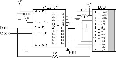
The last LCD Interface macro is designed for the two-wire LCD interface which is shown in the graphic below:
LCD2 Macro ClockPort, ClockPin, DataPort, DataPin, Freq
 variable Dlay5Value, Dlay160Value, Dlay160Bit1 = -1, Dlay160Bit2 = -1
 variable BitCount = 0, i
 variable Value = 128, Bit = 7
Dlay5Value = ((5007 * (Freq / 1000) / 4000) / 7) + 256
Dlay160Value = (163 * (Freq / 1000) / 4000) / 3

 while (Bit >= 0)			;  Find the Number of Bits and their
					;   Positions in "Dlay160Value"
 if ((Dlay160Value & Value) != 0)
 if (Dlay160Bit1 == -1)		;  Set the Upper Bit
Dlay160Bit1 = Bit
 else
 if (Dlay160Bit2 == -1)
Dlay160Bit2 = Bit
 endif
 endif
BitCount = BitCount + 1
 endif
Value = Value >> 1
Bit = Bit - 1
 endw
 if (BitCount > 2)		;  Just Want max two Bits
 if ((Dlay160Bit1 - 1) == Dlay160Bit2)
Dlay160Bit1 = Dlay160Bit1 + 1	;  Shift Top up by 1
Dlay160Bit2 = -1			;  Delete Second
 else
Dlay160Bit2 = Dlay160Bit2 + 1	;  Shift Bottom up by 1
 endif
 endif

Dlay5					;  Delay 5 msecs
  movlw   (Dlay5Value & 0x0FF00) >> 8
  movwf   Dlay
  movlw   Dlay5Value & 0x0FF
  subwf   Dlay, w
  xorlw   0x0FF
  addwf   Dlay, w
  btfsc   STATUS, Z
   decfsz Dlay, f
    goto  $ - 5
  return

LCDPORTInit				;  Initialize the I/O Ports
  bsf     STATUS, RP0		;   ONLY used by mid-range
  bcf     ClockPort, ClockPin
  bcf     DataPort, DataPin
  bcf     STATUS, RP0
  bcf     ClockPort, ClockPin
  bcf     DataPort, DataPin
  return

LCDIns				;  Send the Instruction to the LCD
  movwf   LCDTemp			;  Save the Value
  movlw   6				;  Clear the Shift Register
  movwf   Dlay
  bsf     ClockPort, ClockPin
  bcf     ClockPort, ClockPin
  decfsz  Dlay, f
   goto   $ - 3
  movwf   Dlay			;  w still equals 6
  movf    LCDTemp, w		;  Shift out the Upper 4 Bits
  swapf   LCDTemp, f
  bsf     LCDTemp, 5		;  Make LCDTemp Correct for Shifting
  bcf     LCDTemp, 4		;  This is "RS" Bit
  bcf     DataPort, DataPin	;  Shift Out Each Bit
  btfsc   LCDTemp, 5		;  5 is the Current MSB
   bsf    DataPort, DataPin	;  Shift Out the Next Highest Bit
  bsf     ClockPort, ClockPin
  bcf     ClockPort, ClockPin
  rlf     LCDTemp, f
  decfsz  Dlay, f
   goto   $ - 7
  bsf     DataPort, DataPin	;  Latch in the Data
 if (Freq > 8000000)		;  Make Sure Proper Delay is In Place
 if (Freq < 16000000)
  nop
 else
  goto    $ + 1
 endif
 endif
  bcf     DataPort, DataPin
  bsf     Dlay, 2			;  Dlay = 6 for Shift Out
  bsf     Dlay, 1
  bsf     ClockPort, ClockPin	;  Clear the Shift Register
  bcf     ClockPort, ClockPin
  decfsz  Dlay, f
   goto   $ - 3
  movwf   LCDTemp			;  Shift out the Low Nybble
  bsf     Dlay, 2			;  Dlay = 6 for Shift Out
  bsf     Dlay, 1
  bsf     LCDTemp, 5		;  Make LCDTemp Correct for Shifting
  bcf     LCDTemp, 4		;  This is "RS" Bit
  bcf     DataPort, DataPin	;  Shift Out Each Bit
  btfsc   LCDTemp, 5		;  5 is the Current MSB
   bsf    DataPort, DataPin	;  Shift Out the Next Highest Bit
  bsf     ClockPort, ClockPin
  bcf     ClockPort, ClockPin
  rlf     LCDTemp, f
  decfsz  Dlay, f
   goto   $ - 7
  bsf     DataPort, DataPin	;  Latch in the Data
 if (Freq > 8000000)		;  Make Sure Proper Delay is In Place
 if (Freq < 16000000)
  nop
 else
  goto    $ + 1
 endif
 endif
  bcf     DataPort, DataPin
  bsf     Dlay, Dlay160Bit1	;  Delay 160 usecs
 if (Dlay160Bit2 != -1)
  bsf     Dlay, Dlay160Bit2
 endif
  decfsz  Dlay, f
   goto   $ - 1
  andlw   0x0FC			;  Have to Delay 5 msecs?
  btfsc   STATUS, Z
   call   Dlay5
  return

LCDChar				;  Send the Character to the LCD
  movwf   LCDTemp			;  Save the Value
  movlw   6				;  Clear the Shift Register
  movwf   Dlay
  bsf     ClockPort, ClockPin
  bcf     ClockPort, ClockPin
  decfsz  Dlay, f
   goto   $ - 3
  movwf   Dlay			;  w still equals 6
  movf    LCDTemp, w		;  Shift out the Upper 4 Bits
  swapf   LCDTemp, f
  bsf     LCDTemp, 5		;  Make LCDTemp Correct for Shifting
  bsf     LCDTemp, 4		;  This is "RS" Bit
  bcf     DataPort, DataPin	;  Shift Out Each Bit
  btfsc   LCDTemp, 5		;  5 is the Current MSB
   bsf    DataPort, DataPin	;  Shift Out the Next Highest Bit
  bsf     ClockPort, ClockPin
  bcf     ClockPort, ClockPin
  rlf     LCDTemp, f
  decfsz  Dlay, f
   goto   $ - 7
  bsf     DataPort, DataPin	;  Latch in the Data
 if (Freq > 8000000)		;  Make Sure Proper Delay is In Place
 if (Freq < 16000000)
  nop
 else
  goto    $ + 1
 endif
 endif
  bcf     DataPort, DataPin
  bsf     Dlay, 2			;  Dlay = 6 for Shift Out
  bsf     Dlay, 1
  bsf     ClockPort, ClockPin	;  Clear the Shift Register
  bcf     ClockPort, ClockPin
  decfsz  Dlay, f
   goto   $ - 3
  movwf   LCDTemp			;  Shift out the Low Nybble
  bsf     Dlay, 2			;  Dlay = 6 for Shift Out
  bsf     Dlay, 1
  bsf     LCDTemp, 5		;  Make LCDTemp Correct for Shifting
  bsf     LCDTemp, 4		;  This is "RS" Bit
  bcf     DataPort, DataPin	;  Shift Out Each Bit
  btfsc   LCDTemp, 5		;  5 is the Current MSB
   bsf    DataPort, DataPin	;  Shift Out the Next Highest Bit
  bsf     ClockPort, ClockPin
  bcf     ClockPort, ClockPin
  rlf     LCDTemp, f
  decfsz  Dlay, f
   goto   $ - 7
  bsf     DataPort, DataPin	;  Latch in the Data
 if (Freq > 8000000)		;  Make Sure Proper Delay is In Place
 if (Freq < 16000000)
  nop
 else
  goto    $ + 1
 endif
 endif
  bcf     DataPort, DataPin
  bsf     Dlay, Dlay160Bit1	;  Delay 160 usecs
 if (Dlay160Bit2 != -1)
  bsf     Dlay, Dlay160Bit2
 endif
  decfsz  Dlay, f
   goto   $ - 1
  return

LCDInit				;  Do the 8 Bit Initialization
  call    Dlay5			;  Wait 15 msecs
  call    Dlay5
  call    Dlay5
  movlw   0x023			;  Initialize the I/O Port
  movwf   LCDTemp			;  Save the Value
  movlw   6				;  Clear the Shift Register
  movwf   Dlay
  bsf     ClockPort, ClockPin
  bcf     ClockPort, ClockPin
  decfsz  Dlay, f
   goto   $ - 3
  movwf   Dlay
  bcf     DataPort, DataPin	;  Shift Out Each Bit
  btfsc   LCDTemp, 5		;  5 is the Current MSB
   bsf    DataPort, DataPin	;  Shift Out the Next Highest Bit
  bsf     ClockPort, ClockPin
  bcf     ClockPort, ClockPin
  rlf     LCDTemp, f
  decfsz  Dlay, f
   goto   $ - 7
  bsf     DataPort, DataPin	;  Latch in the Data
 if (Freq > 8000000)		;  Make Sure Proper Delay is In Place
 if (Freq < 16000000)
  nop
 else
  goto    $ + 1
 endif
 endif
  bcf     DataPort, DataPin
  call    Dlay5
  bsf     DataPort, DataPin	;  Send another 0x03 to the LCD
 if (Freq > 8000000)		;  Make Sure Proper Delay is In Place
 if (Freq < 16000000)
  nop
 else
  goto    $ + 1
 endif
 endif
  bcf     DataPort, DataPin
  bsf     Dlay, Dlay160Bit1	;  Delay 160 usecs
 if (Dlay160Bit2 != -1)
  bsf     Dlay, Dlay160Bit2
 endif
  decfsz  Dlay, f
   goto   $ - 1
  movlw   0x022			;  Initialize the I/O Port
  movwf   LCDTemp			;  Save the Value
  movlw   6				;  Clear the Shift Register
  movwf   Dlay
  bsf     ClockPort, ClockPin
  bcf     ClockPort, ClockPin
  decfsz  Dlay, f
   goto   $ - 3
  movwf   Dlay
  bcf     DataPort, DataPin	;  Shift Out Each Bit
  btfsc   LCDTemp, 5		;  5 is the Current MSB
   bsf    DataPort, DataPin	;  Shift Out the Next Highest Bit
  bsf     ClockPort, ClockPin
  bcf     ClockPort, ClockPin
  rlf     LCDTemp, f
  decfsz  Dlay, f
   goto   $ - 7
  bsf     DataPort, DataPin	;  Latch in the Data
 if (Freq > 8000000)		;  Make Sure Proper Delay is In Place
 if (Freq < 16000000)
  nop
 else
  goto    $ + 1
 endif
 endif
  bcf     DataPort, DataPin
  bsf     Dlay, Dlay160Bit1	;  Delay 160 usecs
 if (Dlay160Bit2 != -1)
  bsf     Dlay, Dlay160Bit2
 endif
  decfsz  Dlay, f
   goto   $ - 1
  movlw   0x028			;  Set Interface Length
  call    LCDIns
  movlw   0x010			;  Turn Off Display
  call    LCDIns
  movlw   0x001			;  Clear Display RAM
  call    LCDIns
  movlw   0x006			;  Set Cursor Movement
  call    LCDIns
  movlw   0x00E			;  Turn on Display/Cursor
  call    LCDIns
  return
 endm
2. NRZ Serial I/O
The two macros which follow will give you two different ways of providing NRZ serial communications using your PICmicro application. These macros will provide you with serial transmit and receive functions which work as both positive and negative logic.
The first macro provides a straight "bit-banging" serial interface. Note that it requires the DlayMacro.
NRZSerialNI Macro TXPort, TXPin, RXPort, RXPin, Polarity, Rate, Frequency
 variable BitDlay
BitDlay = Frequency / (4 * Rate)

SerialRX				;  Receive 8-N-1
 if (Polarity == Pos)
  btfsc  RXPort, RXPin		;  Wait for a Bit to Come in
 else
  btfss  RXPort, RXPin
 endif
   goto  $ - 1

 DlayMacro BitDlay / 2		;  Wait 1/2 a Bit to Confirm

 if (Polarity == Pos)
  btfsc  RXPort, RXPin		;  Confirm Data is Correct
 else
  btfss  RXPort, RXPin
 endif
   goto  SerialRX			;  If Just a "Glitch", Restart Start Bit
;   Poll
  movlw  8				;  Wait for 8 Bits
SRXLoop
 if ((BitDlay - 10) > 770)	;  Check to See if Value is Too Large
 DlayMacro 770			;  Put in a "Double" Delay
 DlayMacro BitDlay - (770 + 10)
 else
 DlayMacro BitDlay - 10		;  Wait for the Middle of the Next Bit
 endif

  bcf    STATUS, C		;  Check the Incoming Data
 if (Polarity == Pos)
  btfsc  RXPort, RXPin
 else
  btfss  RXPort, RXPin
 endif
   bsf   STATUS, C
  rrf    NRZTemp, f		;  Shift in the Bit

  subwf  NRZTemp, w		;  Decrement and End if == 0
  xorlw  0x0FF
  addwf  NRZTemp, w
  btfss  STATUS, Z
   goto  SRXLoop

 if ((BitDlay - 9) > 770)	;  Check to See if Value is Too Large
 DlayMacro 770			;  Put in a "Double" Delay
 DlayMacro BitDlay - (770 + 9)
 else
 DlayMacro BitDlay - 9		;  Wait for the Middle of the Next Bit
 endif

 if (Polarity == Pos)		;  Is there a Stop Bit?
  btfss  RXPort, RXPin
 else
  btfsc  RXPort, RXPin
 endif
   goto  SerialRX			;  No, Start All Over Again

  movf   NRZTemp, w		;  Return the Received Byte
  return				;   Note - Zero Returned in Low-End
;   Devices

SerialTX
  movwf  NRZTemp			;  Save the Byte to Output
  movlw  10
  bcf    STATUS, C		;  Start with Sending the Start Bit
STXLoop
 if (Polarity == Pos)		;  Output the Current Bit
  btfsc  STATUS, C
 else
  btfss  STATUS, C
 endif
   goto  $ + 4			;  6 Cycles Required Each Time
  nop
  bcf    TXPort, TXPin		;  Output a "Low"
  goto   $ + 3
  bsf    TXPort, TXPin		;  Output a "High"
  goto   $ + 1
 if ((BitDlay - 15) > 770)	;  Check to See if Value is Too Large
 DlayMacro 770			;  Put in a "Double" Delay
 DlayMacro BitDlay - (770 + 15)
 else
 DlayMacro BitDlay - 15		;  Wait for the Middle of the Next Bit
 endif
  subwf  NRZTemp, w		;  Decrement the Bit Counter
  xorlw  0x0FF
  addwf  NRZTemp, w
  btfsc  STATUS, Z
   return				;  Can Return to Caller
  bsf    STATUS, C		;  Shift Down the Next Bit
  rrf    NRZTemp, f
  goto   STXLoop
 endm
If you are working with a mid-range PICmicro, you can also invoke the ōNRZSerialNISetupö macro that creates the ōSerialSetupö subroutine. This subroutine puts the TX pin in ōoutput modeö and drives an ōidleö output. This subroutine should be executed as early as possible after the application has started. This will ensure that the PICmicro does not inadvertently cause the receiver to process invalid data by missing the first ōStart Bitö.
NRZSerialNISetup Macro TXPort, TXPin, Polarity
SerialSetup				;  Setup the Serial I/O Bits
  bsf    STATUS, RP0
  bcf    TXPort, TXPin		;  Make TX Pin an Output
  bcf    STATUS, RP0
 if (Polarity == Pos)
  bsf    TXPort, TXPin		;  Transmit "idle"
 else
  bcf    TXPort, TXPin
 endif
  return
 endm
The last macro will provide you with a TMR0 based interrupt polling routine which will run in the "background" of your application. This is the recommended macro for mid-range PICmicro MCU Serial Communications:
NRZSerialI Macro TXPort, TXPin, RXPort, RXPin, Polarity, Rate, Frequency
 variable BitDlay, Prescaler, TMR0Reset
BitDlay = (Frequency / (3 * 4 * Rate)) - 10
TMR0Reset = BitDlay / 2		;  Using TMR0, Calculate the Timer Reset Value
Prescaler = 0			;  And the Prescaler
 while (TMR0Reset > 0x0FF)	;  Find the Proper Reset Value
TMR0Reset = TMR0Reset / 2
Prescaler = Prescaler + 1
 endw
 if (Prescaler > 7)		;  Can't Use TMR0
 error "Bit Delay cannot use TMR0 for Polling Clock"
 endif
TMR0Reset = 256 - TMR0Reset	;  Get the TMR0 Reset Value

  goto   AfterInt			;  Jump to After Interrupt
 org     4
Int					;  Interrupt Handler
  movwf  _w
  movf   STATUS, w
  bcf    STATUS, RP0		;  Make Sure in Bank 0
  movwf  _status

  bcf    INTCON, T0IF		;  Reset the Timer Interrupt

  movlw  TMR0Reset
  movwf  TMR0

;  First, Check for a Received Character
Int_RX

  movlw  0x004			;  Check for Bit?
  addwf  RXCount, f
  btfss  STATUS, DC		;  DC Not Affected by "clrf
   goto  _RXNo			;  Nothing to Check for (Yet)

  movf   RXCount, w		;  Everything Read Through?
  xorlw  0x091
  btfsc  STATUS, Z
   goto  _RXAtEnd			;  Yes, Check for Stop Bit

  bcf    STATUS, C		;  Read the Current State
 if (Polarity == Pos)
  btfsc  RXPort, RXPin		;  Sample at 10 Cycles
 else
  btfss  RXPort, RXPin
 endif
   bsf   STATUS, C
  rrf    RXByte, f

  bsf    RXCount, 2		;  Start Counting from 4

_RXEnd13
  nop
  goto   _RXEnd			;  End 15 Cycles From "Int_RX" - Finished Receiving Bit

_RXEnd8				;  Finished - 8 Cycles to Here
  goto   $ + 1
  nop
  goto   _RXEnd13

_RXNo					;  5 Cycles from "Int_RX" - No Bit to Receive

  btfsc  RXCount, 0		;  Something Running?
   goto  _RXEnd8			;  End 8 Cycles from "Int_RX" - Yes, Skip Over

  btfsc  RXCount, 3		;  Checking Start Bits?
   goto  _RXStartCheck

 if (Polarity == Pos)
  btfsc  RXPort, RXPin		;  If Line Low - "Start" Bit
 else
  btfss  RXPort, RXPin
 endif
   bcf   RXCount, 2		;  Don't Have a "Start" Bit

  goto   _RXEnd13			;  End 18 cycles from "Int_RX"

_RXStartCheck			;  10 Cycles to Here

 if (Polarity == Pos)
  btfsc  RXPort, RXPin
 else
  btfss  RXPort, RXPin
 endif
   movlw 0x0FF			;  Nothing - Clear "RXCount"

  addlw  1
  movwf  RXCount

  goto   _RXEnd			;  16 Cycles to End

_RXAtEnd				;  9 Cycles from "Int_RX" - Check Last
;   Bit
 if (Polarity == Pos)
  btfsc  RXPort, RXPin
 else
  btfss  RXPort, RXPin
 endif
   bsf   RXFlag

  clrf   RXCount			;  Finished - Reset Check - 12 Cycles

  goto   $ + 1
  goto   _RXEnd

_RXEnd

;  Next, Check for Transmitting a Character - Intrinsic Dlay 22 Cycles
Int_TX

  movlw  0x004			;  Interrupt Transmit Increment Value
  addwf  TXCount, f
  btfss  STATUS, DC		;  Send the Next Byte?
   goto  _TXSendDlayCheck

  bsf    TXCount, 2		;  Want to Increment 3x not Four for each Bit

  bsf    STATUS, C
  rrf    TXByte, f

  movf   TXPort, w		;  Send Next Bit
  andlw  0x0FF ^ (1 << TXPin)
 if (Polarity == Pos)
  btfsc  STATUS, C
 else
  btfss  STATUS, C
 endif
   iorlw 1 << TXPin
  movwf  TXPort			;  Cycle 12 is the Bit Send

  goto   _TXCompletedGoOn	;  TX Takes 14 Cycles

_TXSendDlayCheck			;  Don't Send Bit, Check for Start Bit

  btfss  TXCount, 0		;  Bit Zero Set (Byte to Send)?
   goto  _TXNothingtoCheck

  movlw  0x004			;  Setup the Timer to Increment 3x
  movwf  TXCount

  movf   TXPort, w		;  Output Start Bit
 if (Polarity == Pos)
  andlw  0x0FF ^ (1 << TXPin)
 else
  iorlw  1 << TXPin
 endif
  movwf  TXPort

  goto   _TXCompletedGoOn	;  TX First Bit Takes 14 Cycles

_TXNothingtoCheck			;  Nothing Being Sent?

  movf   TXCount, w
  xorlw  0x004			;  Zero (Originally) TXCount?
  btfss  STATUS, Z
   xorlw 0x004 ^ 0x09C
  btfsc  STATUS, Z
   clrf  TXCount

_TXCompletedGoOn			;  Finished with TX, Do RX

  movf   _status, w		;  Restore the Interrupts
  movwf  STATUS
  swapf  _w, f
  swapf  _w, w
  retfie

SerialRX

  bcf    RXFlag			;  Reset the

  btfss  RXFlag			;  Wait for a Character to be Received
   goto  $ - 1

  movf   RXByte, w		;  Return the Character Read in

  return

SerialTX

  movf   TXCount, f		;  Anything Being Sent?
  btfss  STATUS, Z		;  Wait for the Previous Send to End
   goto  $ - 2

  movwf  TXByte			;  Send out the Character

  bsf    TXCount, 0		;  Indicate to the Interrupt Handler
                              ;   that it can Send Something
  return

AfterInt				;  Can Return the Value
  bsf    STATUS, RP0		;  Setup the Interrupts/TX Output
  bcf    TXPort, TXPin
  movlw  0x0D0 + Prescaler
  movwf  OPTION_REG ^ 0x080	;  User Prescaler with TMR0
  bcf    STATUS, RP0
 if (Polarity == Pos)
  bsf    TXPort, TXPin		;  Output "Idle" for Data Transmit
 else
  bcf    TXPort, TXPin
 endif
  movlw  TMR0Reset		;  Reset the Timer
  movwf  TMR0
  movlw  (1 << GIE) + (1 << T0IE)
  movwf  INTCON			;  Start up the Interrupts

  clrf   RXCount		;  Make Sure No Counts are Starting
  clrf   TXCount

 endm
Along with the macro invocation, the following variables will have to be declared for the code to work:
_w, _status       - Interrupt Handler Context Save Registers
RXByte, TXByte    - Data Transmit and Receive Bytes
RXCount, TXCount  - Serial Transfer Data Count/Status Variables
Flags             - Execution Flag Variable
3. Mid-Range I2C Device Interface
Here is a macro I have developed which provides I2C "Single-Master" capability to the mid-range PICmicro:
I2CSetup Macro ClockPort, ClockPin, DataPort, DataPin, Rate, Frequency
 variable Dlay, Fraction	;  Delay in Instruction Cycles
Dlay = ((Frequency * 110) / (800 * Rate)) / 1000
Fraction = ((Frequency * 110) / (800 * Rate)) - (Dlay * 1000)
 if (Fraction > 499)
Dlay = Dlay + 1
 endif

I2CBitSetup				;  Setup I2C Lines for Application
  bsf    STATUS, RP0
  bcf    ClockPort, ClockPin	;  Driving Output
  bcf    DataPort, DataPin
  bcf    STATUS, RP0
  bsf    ClockPort, ClockPin	;  Everything High Initially
  bsf    DataPort, DataPin
 DlayMacro Dlay			;  Make Sure Lines are High for adequate
                              ;   Period of Time
  return

I2CStart				;  Send a "Start" Pulse to the I2C Device
  bsf    ClockPort, ClockPin
  bsf    DataPort, DataPin
 DlayMacro Dlay - 2
  bcf    DataPort, DataPin	;  Drop the Data Line
 DlayMacro Dlay
  bcf    ClockPort, ClockPin	;  Drop the Clock Line
 DlayMacro Dlay - 2		;  Wait for the Specified Period
  return				;  Exit with Clock = Low, Data = Low

I2CStop				;  Pass Stop Bit to I2C Device
 DlayMacro Dlay
  bsf    ClockPort, ClockPin	;  Clock Bit High
 DlayMacro Dlay
  bsf    DataPort, DataPin
  return				;  Exit with Clock = High, Data = High

I2CRead				;  Read 8 Bits from the Line
					;   Reply with "ACK" in Carry Flag
  bsf    I2CTemp, 0		;  Put in the Carry Flag
  btfsc  STATUS, C
   bcf   I2CTemp, 0		;  If Carry Set, then Send "Ack" (-ative)
  bsf    STATUS, RP0		;  Let the I2C Device Drive the Data Line
  bsf    DataPort, DataPin
  bcf    STATUS, RP0
  movlw  0x010 - 8
I2CRLoop
  bsf    ClockPort, ClockPin	;  Bring the Clock Line Up
 DlayMacro (Dlay / 2) - 1
  bcf    STATUS, C
  btfsc  DataPort, DataPin	;  Sample the Incoming Data
   bsf   STATUS, C
 DlayMacro (Dlay / 2) - 2
  bcf    ClockPort, ClockPin
  rlf    I2CTemp, f		;  Shift in the Bit
  andlw  0x07F			;  Store the Ack of Bit 7 of the Data
  btfsc  STATUS, C
   iorlw 0x080			;  If High, Set Bit 7
  addlw  0x001			;  Finished, Do the Next Bit
 DlayMacro Dlay - 9		;  Put in "TLow"
  btfss  STATUS, DC
   goto  I2CRLoop
  bcf    DataPort, DataPin
  bsf    STATUS, RP0		;  Send Ack Bit
  bcf    DataPort, DataPin
  bcf    STATUS, RP0
  andlw  0x080			;  High or Low?
  btfss  STATUS, Z
   bsf   DataPort, DataPin	;  Low, Send Ack
 DlayMacro Dlay / 18		;  Any Reason to delay?
  bsf    ClockPort, ClockPin
 DlayMacro Dlay
  bcf    ClockPort, ClockPin
  bcf    DataPort, DataPin
  movf   I2Ctemp, w		;  Get the Received Byte
  return				;  Return with Clock = Data = Low

I2CSend				;  Send the 8 Bits in "w" and Return Ack
  movwf  I2CTemp
  movlw  0x010 - 8
I2CSLoop
  rlf    I2CTemp, f		;  Shift up the Data into "C"
  btfsc  STATUS, C
   goto  $ + 4
  nop
  bcf    DataPort, DataPin	;  Low Bit
  goto   $ + 3
  bsf    DataPort, DataPin	;  High Bit
  goto   $ + 1
  bsf    ClockPort, ClockPin	;  Strobe Out the Data
 DlayMacro Dlay
  bcf    ClockPort, ClockPin
 DlayMacro Dlay - 12
  addlw  1
  btfss  STATUS, DC
   goto  I2CSLoop
 DlayMacro 6
  bsf    STATUS, RP0		;  Now, Get the Ack Bit
  bsf    DataPort, DataPin
  bcf    STATUS, RP0
  bsf    ClockPort, ClockPin
 DlayMacro (Dlay / 2) - 1
  bcf    STATUS, C
  btfss  DataPort, DataPin
   bsf   STATUS, C		;  Line Low, "Ack" Received
 DlayMacro (Dlay / 2) - 2
  bsf    STATUS, RP0
  bcf    DataPort, DataPin
  bcf    STATUS, RP0
  bcf    ClockPort, ClockPin
  bcf    DataPort, DataPin
  return				;  Return with Ack in Carry,
 endm					;   Clock = Data = Low